Sweeper Module
The Sweeper Module allows the user to perform sweeps as in the Sweeper Tab of the LabOne User Interface. In general, the Sweeper can be used to obtain data when measuring a DUT's response to varying (or sweeping) one instrument setting while other instrument settings are kept constant.
Configuring the Sweeper
In this section we briefly describe how to configure the Sweeper Module. See the node documentation for a full list of the Sweeper's parameters and description of the Sweeper's outputs.
Specifying the Instrument Setting to Sweep
The Sweeper's gridnode parameter, the so-called sweep parameter,
specifies the instrument's setting to be swept, specified as a path to
an instrument's node.
This is typically an oscillator frequency in a
Frequency Response Analyzer, e.g., /DEV2345/OSCS/0/FREQ, but a wide
range of instrument settings can be chosen, such as a signal output amplitude
or a PID controller's setpoint.
Specifying the Range of Values for the Sweep Parameter
The Sweeper will change the sweep parameter's value samplecount times
within the range of values specified by start and stop. The
xmapping parameter specifies whether the spacing between two
sequential values in the range is linear (=0) or logarithmic (=1).
Controlling the Scan mode: The Selection of Range Values
The scan parameter defines the order that the values in the
specified range are written to the sweep parameter. In sequential scan mode (=0),
the sweep parameter's values change incrementally from
smaller to larger values. In order
to scan the sweep parameter's in the opposite direction, i.e., from
larger to smaller values, reverse scan mode (=3) can be used.
In binary scan mode (=1) the first sweep parameter's value is taken as
the value in the middle of the range, then the range is split into two
halves and the next two values for the sweeper parameter are the values
in the middle of those halves. This process continues until all the
values in the range were assigned to the sweeper parameter. Binary scan
mode ensures that the sweep parameter uses values from the entire range
near the beginning of a measurement, which allows the user to get
feedback quickly about the measurement's entire range.
In bidirectional scan mode (=2) the sweeper parameter's values are first
set from smaller to larger values as in sequential mode, but are then
set in reverse order from larger to smaller values. This
allows for effects in the sweep parameter to be observed that depend on
the order of changes in the sweep parameter's values.
Controlling how the Sweeper sets the Demodulator's Time Constant
The bandwidthcontrol parameter specifies which demodulator filter
bandwidth (equivalently time constant) the Sweeper should set for the
current measurement point. The user can either specify the bandwidth
manually (=0), in which case the value of the current demodulator
filter's bandwidth is simply used for all measurement points; specify a
fixed bandwidth (=1), specified by bandwidth, for all measurement
points; or specify that the Sweeper sets the demodulator's bandwidth
automatically (=2). Note, to use either Fixed or Manual mode,
bandwidth must be set to a value > 0 (even though in manual mode it is
ignored).
Specifying the Sweeper's Settling Time
For each change in the sweep parameter that takes effect on the
instrument the Sweeper waits before recording measurement data in order
to allow the measured signal to settle. This behavior is configured by
two parameters in the settling/ branch: settling/time and
settling/inaccuracy.
The settling/time parameter specifies the minimum time in seconds to
wait before recording measurement data for that sweep point. This can be
used to specify to the settling time required by the user's experimental
setup before measuring the response in their system.
The settling/inaccuracy parameter is used to derive the settling time
to allow for the lock-in amplifier's demodulator filter response to
settle following a change of value in the sweep parameter. More
precisely, the settling/inaccuracy parameter specifies the amount of
settling time as the time required to attain the specified remaining
proportion [1e-13, 0.1] of an incoming step function. Based upon the
value of settling/inaccuracy and the demodulator filter order, the
number of demodulator filter time constants to wait is calculated and
written to settling/tc (upon calling the module's execute() command)
which can then be read back by the user. See
<settling/inaccuracy. The relationship between settling/inaccuracy
and settling/tc is the following:

The actual amount of time the Sweeper Module will wait after setting a
new sweep parameter value before recording measurement data is defined
in Equation 1. For a
frequency sweep, the settling/inaccuracy parameter will tend to
influence the settling time at lower frequencies, whereas
settling/time will tend to influence the settling time at higher
frequencies.
The settling time t~s~ used by the Sweeper for each measurement point; the amount of time between setting the sweep parameter and recording measurement data is determined by the settling/tc and settling/time (see Equation 1).
Note
Note, although it is recommended to use settling/inaccuracy, it is
still possible to set the settling time via settling/tc instead of
settling/inaccuracy (the parameter applied will be simply the last one
that is set by the user).
Specifying which Data to Measure
Which measurement data is actually returned by the Sweeper's read
command is configured by subscribing to node paths using the Sweeper Module's
subscribe command.
Specifying how the Measurement Data is Averaged
One Sweeper measurement point is obtained by averaging recorded data
which is configured via the parameters in the averaging/ branch.
The averaging/tc parameter specifies the minimum time window in
factors of demodulator filter time constants during which samples will
be recorded in order to average for one returned sweeper measurement
point. The averaging/sample parameter specifies the minimum number of
data samples that should be recorded and used for the average. The
Sweeper takes both these settings into account for the measurement
point's average according to
Equation 2.
The number of samples N used to average one sweeper measurement point is determined by the parameters averaging/time, averaging/tc, and averaging/sample as well as the rate of data transfer from the instrument to the data server (see Equation 2).
Note
Note, the value of the demodulator filter's time constant may be
controlled by the Sweeper depending on the value of bandwidthcontrol
and bandwidth, see the respective section above.
For a frequency sweep,
the averaging/tc parameter will tend to influence the number of
samples recorded at lower frequencies, whereas averaging/sample will
influence averaging behavior at higher frequencies.
An Explanation of Settling and Averaging Times in a Frequency Sweep
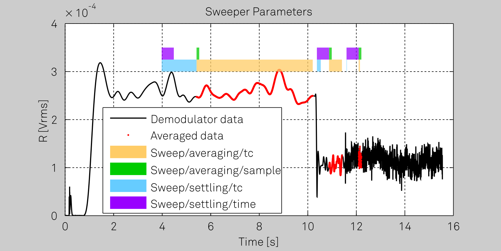
The image shows which demodulator samples are used in order to calculate an averaged measurement point in a frequency sweep. This explanation of the Sweeper's parameters is specific to the following commonly-used Sweeper settings:
gridnodeis set to an oscillator frequency, e.g.,/dev123/oscs/0/freq.bandwidthcontrolis set to 2, corresponding to automatic bandwidth control, i.e., the Sweeper will set the demodulator's filter bandwidth settings optimally for each frequency used.scanis set to 0, corresponding to sequential scan mode for the range of frequency values swept, i.e, the frequency is increasing for each measurement point made.
Each one of the three red segments in the demodulator data correspond to
the data used to calculate one single Sweeper measurement point. The
light blue bars correspond to the time the sweeper should wait as
indicated by settling/tc (this is calculated by the Sweeper Module
from the specified settling/inaccuracy parameter). The purple bars
correspond to the time specified by the settling/time parameter. The
sweeper will wait for the maximum of these two times according to
Equation 1. When
measuring at lower frequencies the Sweeper sets a smaller demodulator
filter bandwidth (due to automatic bandwidthcontrol) corresponding to
a larger demodulator filter time constant. Therefore, the settling/tc
parameter dominates the settling time used by the Sweeper at low
frequencies and at high frequencies the settling/time parameter takes
effect. Note, that the light blue bars corresponding to the value of
settling/tc get shorter for each measurement point (larger frequency
used -> shorter time constant required), whereas the purple bars
corresponding to settling/time stay a constant length for each
measurement point. Similarly, the averaging/tc parameter (yellow bars)
dominates the Sweeper's averaging behavior at low frequencies, whereas
averaging/samples (green bars) specifies the behavior at higher
frequencies, see also
Equation 2.
Average Power and Standard Deviation of the Measured Data
The Sweeper returns measurement data upon calling the Sweeper's read()
function. This returns not only the averaged measured samples (e.g. r)
but also their average power (rpwr) and standard deviation
(rstddev). In order to obtain reliable values from this statistical
data, please ensure that the averaging branch parameters are
configured correctly. It's recommended to use at least a value of 12 for
averaging/sample to ensure enough values are used to calculate the
standard deviation and 5 for averaging/tc in order to prevent aliasing
effects from influencing the result.
Node Documentation
This section describes all the nodes in the Sweeper Module node tree organized by branch.
averaging
/averaging/sample 
| Properties: | Read, Write |
| Type: | Integer (64 bit) |
| Unit: | Samples |
Sets the number of data samples per sweeper parameter point that is considered in the measurement.
/averaging/tc 
| Properties: | Read, Write |
| Type: | Double |
| Unit: | TC |
Sets the effective number of time constants per sweeper parameter point that is considered in the measurement.
/averaging/time 
| Properties: | Read, Write |
| Type: | Double |
| Unit: | Seconds |
Sets the effective measurement time per sweeper parameter point that is considered in the measurement.
awgcontrol
/awgcontrol 
| Properties: | Read, Write |
| Type: | Integer (64 bit) |
| Unit: | None |
Enable AWG control for sweeper. If enabled the sweeper will automatically start the AWG and records the sweep sample based on the even index in hwtrigger.
bandwidth
/bandwidth 
| Properties: | Read, Write |
| Type: | Double |
| Unit: | Hz |
Defines the measurement bandwidth when using Fixed bandwidth mode (sweep/bandwidthcontrol=1), and corresponds to the noise equivalent power bandwidth (NEP).
bandwidthcontrol
/bandwidthcontrol 
| Properties: | Read, Write |
| Type: | Integer (enumerated) |
| Unit: | None |
Specify how the sweeper should specify the bandwidth of each measurement point. Automatic is recommended, in particular for logarithmic sweeps and assures the whole spectrum is covered.
| Value | Description |
|---|---|
| 0 | "manual": Manual (the sweeper module leaves the demodulator bandwidth settings entirely untouched) |
| 1 | "fixed": Fixed (use the value from sweep/bandwidth) |
| 2 | "auto": Automatic. Note, to use either Fixed or Manual mode, sweep/bandwidth must be set to a value > 0 (even though in manual mode it is ignored). |
bandwidthoverlap
/bandwidthoverlap 
| Properties: | Read, Write |
| Type: | Integer (64 bit) |
| Unit: | None |
If enabled the bandwidth of a sweep point may overlap with the frequency of neighboring sweep points. The effective bandwidth is only limited by the maximal bandwidth setting and omega suppression. As a result, the bandwidth is independent of the number of sweep points. For frequency response analysis bandwidth overlap should be enabled to achieve maximal sweep speed.
clearhistory
/clearhistory 
| Properties: | Read, Write |
| Type: | Integer (64 bit) |
| Unit: | None |
Remove all records from the history list.
device
/device 
| Properties: | Read, Write |
| Type: | String |
| Unit: | None |
The device ID to perform the sweep on, e.g., dev1000 (compulsory parameter, this parameter must be set first).
endless
/endless 
| Properties: | Read, Write |
| Type: | Integer (64 bit) |
| Unit: | None |
Enable Endless mode; run the sweeper continuously.
filtermode
/filtermode 
| Properties: | Read, Write |
| Type: | Integer (enumerated) |
| Unit: | None |
Selects the filter mode.
| Value | Description |
|---|---|
| 0 | "application": Application (the sweeper sets the filters and other parameters automatically) |
| 1 | "advanced": Advanced (the sweeper uses manually configured parameters) |
gridnode
/gridnode 
| Properties: | Read, Write |
| Type: | String |
| Unit: | Node |
The device parameter (specified by node) to be swept, e.g., "oscs/0/freq".
historylength
/historylength 
| Properties: | Read, Write |
| Type: | Integer (64 bit) |
| Unit: | None |
Maximum number of entries stored in the measurement history.
loopcount
/loopcount 
| Properties: | Read, Write |
| Type: | Integer (64 bit) |
| Unit: | None |
The number of sweeps to perform.
maxbandwidth
/maxbandwidth 
| Properties: | Read, Write |
| Type: | Double |
| Unit: | Hz |
Specifies the maximum bandwidth used when in Auto bandwidth mode (sweep/bandwidthcontrol=2). The default is 1.25 MHz.
omegasuppression
/omegasuppression 
| Properties: | Read, Write |
| Type: | Double |
| Unit: | dB |
Damping of omega and 2omega components when in Auto bandwidth mode (sweep/bandwidthcontrol=2). Default is 40dB in favor of sweep speed. Use a higher value for strong offset values or 3omega measurement methods.
order
/order 
| Properties: | Read, Write |
| Type: | Integer (64 bit) |
| Unit: | None |
Defines the filter roll off to set on the device in Fixed and Auto bandwidth modes (sweep/bandwidthcontrol=1 and 2). It ranges from 1 (6 dB/octave) to 4 (24 dB/octave) or 8 (48 dB/octave) depending on the device type.
phaseunwrap
/phaseunwrap 
| Properties: | Read, Write |
| Type: | Integer (64 bit) |
| Unit: | None |
Enable unwrapping of slowly changing phase evolutions around the +/-180 degree boundary.
remainingtime
/remainingtime 
| Properties: | Read |
| Type: | Double |
| Unit: | Seconds |
Reports the remaining time of the current sweep. A valid number is only displayed once the sweeper has been started. An undefined sweep time is indicated as NAN.
samplecount
/samplecount 
| Properties: | Read, Write |
| Type: | Integer (64 bit) |
| Unit: | None |
The number of measurement points to set the sweep on.
save
/save/csvlocale 
| Properties: | Read, Write |
| Type: | String |
| Unit: | None |
The locale to use for the decimal point character and digit grouping character for numerical values in CSV files: "C": Dot for the decimal point and no digit grouping (default); "" (empty string): Use the symbols set in the language and region settings of the computer.
/save/csvseparator 
| Properties: | Read, Write |
| Type: | String |
| Unit: | None |
The character to use as CSV separator when saving files in this format.
/save/directory 
| Properties: | Read, Write |
| Type: | String |
| Unit: | None |
The base directory where files are saved.
/save/fileformat 
| Properties: | Read, Write |
| Type: | Integer (enumerated) |
| Unit: | None |
The format of the file for saving data.
| Value | Description |
|---|---|
| 0 | "mat": MATLAB |
| 1 | "csv": CSV |
| 2 | "zview": ZView (Impedance data only) |
| 3 | "sxm": SXM (Image format) |
| 4 | "hdf5": HDF5 |
/save/filename 
| Properties: | Read, Write |
| Type: | String |
| Unit: | None |
Defines the sub-directory where files are saved. The actual sub-directory has this name with a sequence count (per save) appended, e.g. daq_000.
/save/save 
| Properties: | Read, Write |
| Type: | Integer (64 bit) |
| Unit: | None |
Initiate the saving of data to file. The saving is done in the background. When the save has finished, the module resets this parameter to 0.
/save/saveonread 
| Properties: | Read, Write |
| Type: | Integer (64 bit) |
| Unit: | None |
Automatically save the data to file immediately before reading out the data from the module using the read() command. Set this parameter to 1 if you want to save data to file when running the module continuously and performing intermediate reads.
scan
/scan 
| Properties: | Read, Write |
| Type: | Integer (enumerated) |
| Unit: | None |
Selects the scanning type.
| Value | Description |
|---|---|
| 0 | "sequential": Sequential (incremental scanning from start to stop value) |
| 1 | "binary": Binary (Non-sequential sweep continues increase of resolution over entire range) |
| 2 | "bidirectional": Bidirectional (Sequential sweep from Start to Stop value and back to Start again) |
| 3 | "reverse": Reverse (reverse sequential scanning from stop to start value) |
settling
/settling/inaccuracy 
| Properties: | Read, Write |
| Type: | Double |
| Unit: | None |
Demodulator filter settling inaccuracy defining the wait time between a sweep parameter change and recording of the next sweep point. The settling time is calculated as the time required to attain the specified remaining proportion [1e-13, 0.1] of an incoming step function. Typical inaccuracy values: 10m for highest sweep speed for large signals, 100u for precise amplitude measurements, 100n for precise noise measurements. Depending on the order of the demodulator filter the settling inaccuracy will define the number of filter time constants the sweeper has to wait. The maximum between this value and the settling time is taken as wait time until the next sweep point is recorded. See programming manual for the relationship between sweep/settling/inaccuracy and sweep/settling/tc.
/settling/tc 
| Properties: | Read, Write |
| Type: | Double |
| Unit: | TC |
Minimum wait time in factors of the time constant (TC) between setting the new sweep parameter value and the start of the measurement. This filter settling time is derived from sweep/settling/inaccuracy. The maximum between this value and sweep/settling/time is taken as effective settling time. Note, although it is recommended to use sweep/settling/inaccuracy, it is still possible to set sweep/settling/tc directly (the parameter applied will be simply the last one set).
/settling/time 
| Properties: | Read, Write |
| Type: | Double |
| Unit: | Seconds |
Minimum wait time in seconds between setting the new sweep parameter value and the start of the measurement. The maximum between this value and sweep/settling/tc is taken as effective settling time.
sincfilter
/sincfilter 
| Properties: | Read, Write |
| Type: | Integer (64 bit) |
| Unit: | None |
Enables the sinc filter if the sweep frequency is below 50 Hz. This will improve the sweep speed at low frequencies as omega components do not need to be suppressed by the normal low pass filter.
start
startdelay
/startdelay 
| Properties: | Read, Write |
| Type: | Double |
| Unit: | Seconds |
Sets the wait time in seconds between setting the first sweep parameter value and the start of the measurement.
stop
xmapping
/xmapping 
| Properties: | Read, Write |
| Type: | Integer (enumerated) |
| Unit: | None |
Selects the spacing of the grid used by sweep/gridnode (the sweep parameter).
| Value | Description |
|---|---|
| 0 | "linear": Linear |
| 1 | "log": Logarithmic distribution of sweep parameter values |