External Reference
Note
This tutorial is applicable to all UHFLI instruments and to UHFAWG instruments with the UHF-LI option installed. No other options are required. Some settings depend on whether the UHF-MF Multi-frequency option is installed, and the differences are pointed out where necessary.
Preparation
This tutorial explains how to perform demodulation using an external reference frequency. An external reference will be simulated by using one of the internal oscillators. The signal from this internal oscillator will be fed to one of the signal outputs and then fed back in using various connections in order to reference another internal oscillator used for demodulation.
First of all, connect the Signal Output 2 connector to both Signal Input 1 and to the Ref/Trigger Input 1 connector using two BNC cables and a BNC T-junction. The measurement setup is shown in the following figure.

Connect the cables as described above. Make sure that the UHF unit is powered on and connected by USB to your host computer or by Ethernet to your local area network (LAN) where the host computer resides. After starting LabOne the default web browser opens with the LabOne graphical user interface.
The tutorial can be started with the default instrument configuration (e.g. after a power cycle) and the default user interface settings (i.e. as is after pressing F5 in the browser).
Generate the Reference Signal
In this section you generate a 30.0 MHz signal oscillating between 0 V and +/-0.5 V on Output 2 for use as the external reference. Table 1 and Table 2 summarize the instrument settings for generating and measuring the reference signal without and with installed UHF-MF Multi-frequency option.
| Tab | Sub-tab | Section | # | Label | Setting / Value / State |
|---|---|---|---|---|---|
| Lock-in | All | Signal Outputs | 2 | Range | 1.5 V |
| Lock-in | All | Signal Outputs | 2 | Amplitude | 1.0 V |
| Lock-in | All | Signal Outputs | 2 | Offset | 0.0 |
| Lock-in | All | Signal Outputs | 2 | On | ON |
| Lock-in | All | Oscillators | 2 | Frequency | 30 MHz |
| Lock-in | All | Data Transfer | 5 | Enable | ON |
| Lock-in | All | Input | 2 | Range | 1.5 V |
| Lock-in | All | Input | 2 | AC | ON |
| Lock-in | All | Input | 2 | 50 Ω | ON |
| Tab | Sub-tab | Section | # | Label | Setting / Value / State |
|---|---|---|---|---|---|
| Lock-in | All | Output Amplitudes | 5 | Amp 2 | 1.0 Vpk |
| Lock-in | All | Output Amplitudes | 5 | Amp 2 Enable | ON |
| Lock-in | All | Signal Outputs | 2 | Range | 1.5 V |
| Lock-in | All | Signal Outputs | 2 | Offset | 0.0 |
| Lock-in | All | Signal Outputs | 2 | On | ON |
| Lock-in | All | Oscillators | 2 | Frequency | 30 MHz |
| Lock-in | All | Data Transfer | 5 | Enable | ON |
| Lock-in | All | Input | 2 | Range | 1.5 V |
| Lock-in | All | Input | 2 | AC | ON |
| Lock-in | All | Input | 2 | 50 Ω | ON |
In case the UHF-MF option is installed, note that we use the 5th row of the Output Amplitudes in order to ensure that the generated signal is linked to Oscillator 2. The Oscillator assignment may be changed with the Osc setting in the Demodulators section.
To visualize the signal, we can reconnect the Signal Output 2 with Signal Input 2 and check the signal shape on the Scope using the following settings.
| Tab | Sub-tab | Section | # | Label | Setting / Value / State |
|---|---|---|---|---|---|
| Scope | Control | Vertical | Channel 1 | Signal Input 2 | |
| Scope | Trig | Trigger | Trigger | ON | |
| Scope | Trig | Trigger | Signal | Signal Input 2 | |
| Scope | Trig | Trigger | Level | 0 mV | |
| Scope | Run / Stop | ON |

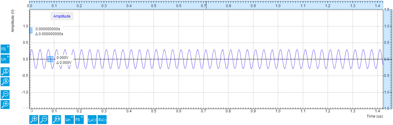
The resulting scope trace should look similar as indicated in the following screen capture.
![]()
Note
Alternatively, the Scope mode Frequency Domain FFT (instead of Time Domain) can be used to check the frequency content of the signal. Set the scale settings automatic for the X axis and logarithmic scale (dB) for the Y axis for convenient viewing. The averaging filter can be set Exp Moving Avg to reduce the noise floor on the display.
Activate the External Reference Mode
After reconnecting the cable as shown in Figure 1 the external reference mode can be activated and output the regenerated signal of interest. The following additional settings have to be adjusted:
| Tab | Sub-tab | Section | # | Label | Setting / Value / State |
|---|---|---|---|---|---|
| Lock-in | All | Data Transfer | 1 | Enable | ON |
| Lock-in | All | Signal Input | 1 | Range | 1.2 V |
| Lock-in | All | Signal Input | 1 | AC | OFF |
| Lock-in | All | Signal Input | 1 | 50 Ω | OFF |
Demodulator 4 and Demodulator 8 can be set to the external reference mode to track the external reference. The external reference can come from the Signal Input 1 and 2, Ref/Trigger 1 and 2 (in the front), Trigger 3 and 4 (on the back), or Aux In 3 and 4 (on the back). The 4 Auxiliary Outputs can also be chosen in the external reference mode although they are not external references. They are useful in the case of tandem demodulation where the result of a first lock-in operation is fed into a second lock-in, typically at a lower frequency. For this tutorial, Sig In 1 is selected as the external reference for Demodulator 4 (i.e. under the Signal column) and activated by selecting ExtRef in the Mode column.
| Tab | Sub-tab | Section | # | Label | Setting / Value / State |
|---|---|---|---|---|---|
| Lock-in | All | Demodulators Input | 4 | Signal | Sig In 1 |
| Lock-in | All | Reference | 4 | Mode | ExtRef |
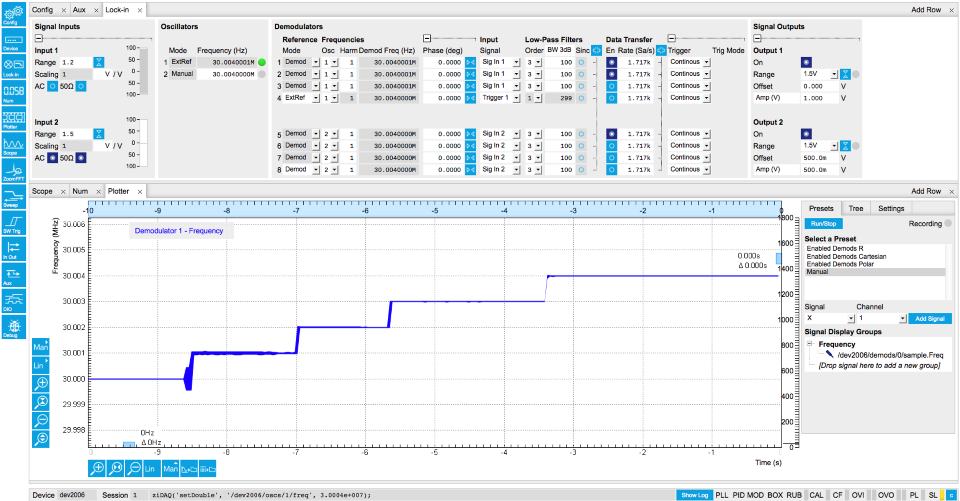
As a result the oscillator 1 frequency indicator in the Oscillator section almost immediately changes from 10 MHz to 30 MHz. Once the external reference mode has been enabled, the frequency of oscillator 1 changes continuously, adapting to the frequency of the external reference signal. This can be verified by changing the frequency of oscillator 2 and noting how the frequency of oscillator 1 follows. A green indicator appears next to the reference selection for channel 1 indicating that the instrument has locked to an external reference. Graphically, this can be visualized in the Plotter by displaying the frequency of Demodulator 1 and then changing the frequency of the oscillator 2 in steps of, say, 1 kHz:
| Tab | Sub-tab | Section | # | Label | Setting / Value / State |
|---|---|---|---|---|---|
| Plotter | Control | Vertical Axis Groups | Tree Selector | /0/sample/Frequency | |
| Plotter | Run / Stop | ON |
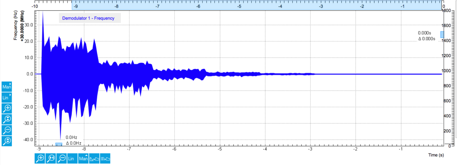
Note that the external reference signal is never used directly for demodulation. Instead, the frequency and phase of the external reference signal is mapped to one of the internal oscillators first through an internal phase-locked loop. This internal oscillator can then serve as a reference for any of the demodulators. This mapping procedure is implemented with an automatic bandwidth adjustment that assures optimum operation over the whole frequency range for a broad variety of signal qualities in terms of frequency stability as well as the signal-to-noise ratio. Over the course of automatic adjustment, the Low-Pass Filter bandwidth of the associated demodulators 4 or 8 usually ramps down until a final value is reached after a few seconds. The indicated bandwidth also marks an upper limit to the bandwidth of the phase-locked loop that does the mapping of the external signal to the internal oscillator. The following figure shows a typical result in the plotter for the frequency tracking immediately after it is turned on.
![]()
Using Ref / Trigger Input and Output for Referencing
In this section you will slightly modify the setup to use Ref / Trigger Input 1 (instrument front panel) as an entry port for the external reference instead of Signal Input 1. A sketch of the modified setup is shown in Figure 6.

There are 2 Ref / Trigger inputs on the front panel of the instrument and two more Trigger inputs on the rear panel. By using the dedicated trigger inputs, both Signal Inputs remain available for measurement. The drawback is that one cannot observe the external reference signal on the Scope tool when a Ref / Trigger inputs are used.
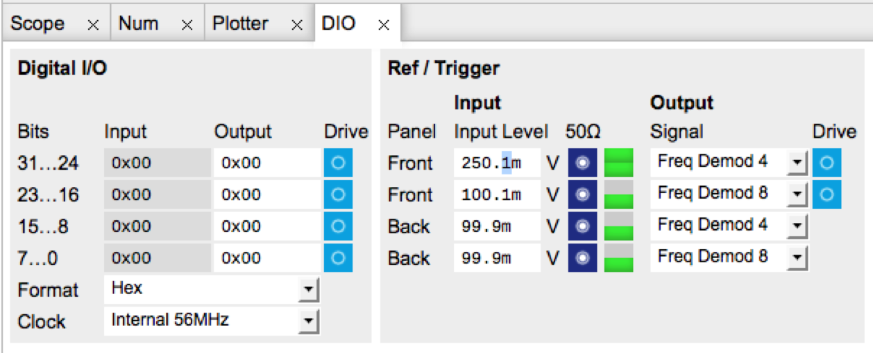
Ref/Trigger Inputs are comparator-based digital channels where the input impedance can be set to either 50 Ω or 1 kΩ in the Ref / Trigger section in the DIO Tab. Moreover, a suitable Trigger threshold can be defined there by adjusting the Input Level setting.
Note
To discriminate the two logical states, the Ref/Trigger input operates with a hysteresis of about 100 mV. Consequently, a peak-to-peak signal amplitude of 200 mV or more should be provided to ensure reliable switching.
Note
For signal frequencies larger than 10 MHz, the 50 Ω input termination is recommended to avoid signal reflections that can lead to false switching events.
When the signal is applied with a proper discrimination threshold chosen, the two rectangular control LEDs will both turn on to indicate that the corresponding channel alternates quickly between high and low logical states. Once this is happening, one can then select Trigger 1 as a Signal Input for demodulator 4 in order to reference oscillator 1. The following settings are used for this example:
| Tab | Sub-tab | Section | # | Label | Setting / Value / State |
|---|---|---|---|---|---|
| DIO | Ref / Trigger | 1 | Input Level | 250 mV | |
| DIO | Ref / Trigger | 1 | 50 Ω | ON | |
| DIO | Ref / Trigger | 1 | Drive | OFF | |
| Lock-in | All | Demodulators Input | 4 | Signal | Trigger 1 |
The default settings are chosen such that a standard 3.3 V TTL signal can be directly attached without further adjustments. This can be easily tested by generating a TTL reference signal on the Trigger outputs on the back panel. A sketch of the modified setup is shown on Figure 8 and the necessary settings are shown in the table below. You should now see as well that the oscillator 1 now tracks the frequency generated from oscillator 2.

| Tab | Sub-tab | Section | # | Label | Setting / Value / State |
|---|---|---|---|---|---|
| DIO | Ref / Trigger | 4 | Signal | Osc φ Demod 8 | |
| DIO | Ref / Trigger | 4 | Drive | ON |