Auxiliary Tab
The Auxiliary tab provides access to the settings of the Auxiliary Inputs and Auxiliary Outputs; it is available on all UHF Series instruments.
Features
- Monitor signal levels of auxiliary input connectors
- Monitor signal levels of auxiliary output connectors
- Auxiliary output signal sources: Demodulators, PIDs, Boxcars, AUs, AWG and manual setting
- Define Offsets and Scaling for auxiliary output values
- Control auxiliary output range limitations
Description
The Auxiliary tab serves mainly to monitor and control the auxiliary inputs and outputs. Whenever the tab is closed or an additional one of the same type is needed, clicking the following icon will open a new instance of the tab.
| Control/Tool | Option/Range | Description |
|---|---|---|
| Aux | Controls all settings regarding the auxiliary inputs and auxiliary outputs. |
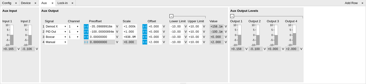
The Auxiliary tab (see Figure 1) is divided into three sections. The Aux Input section gives two graphical and two numerical monitors for the signal amplitude applied to the auxiliary inputs on the back panel. In the middle of the tab the Aux Output section allows to associate any of the measured signals to one of the 4 auxiliary outputs on the instrument front panel. With the action buttons next to the Preoffset and Offset values the effective voltage on the auxiliary outputs can be automatically set to zero. The analog output voltages can be limited to a certain range in order to avoid damaging the parts connected to the outputs.
Note
Please note the change of units of the scaling factor depending on what measurement signal is chosen.
Two Aux Output Levels on the right provides 4 graphical and 4 numerical indicators to monitor the voltages currently set on the auxiliary outputs.
Functional Elements
| Control/Tool | Option/Range | Description |
|---|---|---|
| Auxiliary Input Voltage | -10 V to 10 V | Voltage measured at the Auxiliary Input. |
| Signal | Select the signal source to be represented on the Auxiliary Output. | |
| X | Select the demodulator X component for auxiliary output. | |
| Y | Select the demodulator Y component for auxiliary output. | |
| R | Select the demodulator magnitude component for auxiliary output. | |
| Θ | Select the demodulator phase component for auxiliary output. | |
| PID Out | Select one of the PID controllers output. This needs the UHF-PID option to be installed. | |
| PID Shift | Select one of the PID controllers' shift signal. This needs the UHF-PID option to be installed. | |
| PID Error | Select one of the PID controllers' error signal. This needs the UHF-PID option to be installed. | |
| Boxcar | Select one of the two Boxcar units for auxiliary output. This needs the UHF-BOX option to be installed. | |
| AU Cartesian | Select one of the two Arithmetic Cartesian units for auxiliary output. | |
| AU Polar | Select one of the two Arithmetic Polar units for auxiliary output. | |
| AWG | Select one of the AWG Outputs for auxiliary output when running the AWG in four-channel mode. This needs the UHF-AWG option to be installed. | |
| CNT Out | Select one of the Pulse Counter signals for auxiliary output. This needs the UHF-CNT option to be installed. | |
| Manual | Manually define an auxiliary output voltage using the offset field. | |
| Channel | index | Select the channel according to the selected signal source. |
| Preoffset | numerical value in signal units | Add a pre-offset to the signal before scaling is applied. Auxiliary Output Value = (Signal+Preoffset)*Scale + Offset |
| Auto-zero |  |
Automatically adjusts the Pre-offset to set the Auxiliary Output Value to zero. |
| Scale | numerical value | Multiplication factor to scale the signal. Auxiliary Output Value = (Signal+Preoffset)*Scale + Offset |
| Auto-zero | |
Automatically adjusts the Offset to set the Auxiliary Output Value to zero. |
| Offset | numerical value in Volts | Add the specified offset voltage to the signal after scaling. Auxiliary Output Value = (Signal+Preoffset)*Scale + Offset |
| Lower Limit | -10 V to 10 V | Lower limit for the signal at the Auxiliary Output. A smaller value will be clipped. |
| Upper Limit | -10 V to 10 V | Upper limit for the signal at the Auxiliary Output. A larger value will be clipped. |
| Value | -10 V to 10 V | Voltage present on the Auxiliary Output port. The value is obtained by clamping the calculated signal (Signal+Preoffset)*Scale + Offset based on Lower and Upper Limits. |