Device Node Tree
This chapter contains reference documentation for the settings and
measurement data available on UHF Instruments. Whilst
Functional Description LabOne User Interface
describes many of these settings in terms of the features available in
the LabOne User Interface, this chapter describes them on the device
level and provides a hierarchically organized and comprehensive list of
device functionality.
Since these settings and data streams may be written and read using the
LabOne APIs (Application Programming Interfaces) this chapter is of
particular interest to users who would like to perform measurements
programmatically via LabVIEW, Python, MATLAB, .NET or C.
Please see:
Introduction for an introduction of how the
instrument’s settings and measurement data are organized
hierarchically in the Data Server’s so-called "Node Tree".Reference Node Documentation for a reference list of
the settings and measurement data available on UHF Instruments,
organized by branch in the Node Tree.
Introduction
This chapter provides an overview of how an instrument’s configuration
and output is organized by the Data Server.
All communication with an instrument occurs via the Data Server program
the instrument is connected to (see LabOne Software
Architecture
for an overview of LabOne’s software components). Although the
instrument’s settings are stored locally on the device, it is the Data
Server’s task to ensure it maintains the values of the current settings
and makes these settings (and any subscribed data) available to all its
current clients. A client may be the LabOne User Interface or a user’s
own program implemented using one of the LabOne Application Programming
Interfaces, e.g., Python.
The instrument’s settings and data are organized by the Data Server in a
file-system-like hierarchical structure called the node tree. When an
instrument is connected to a Data Server, its device ID becomes a
top-level branch in the Data Server’s node tree. The features of the
instrument are organized as branches underneath the top-level device
branch and the individual instrument settings are leaves of these
branches.
For example, the auxiliary outputs of the instrument with device ID
"dev2006" are located in the tree in the branch:
/dev1000/auxouts/
In turn, each individual auxiliary output channel has its own branch
underneath the "AUXOUTS" branch.
/dev1000/auxouts/0/ /dev1000/auxouts/1/ /dev1000/auxouts/2/ /dev1000/auxouts/3/
Whilst the auxiliary outputs and other channels are labelled on the
instrument’s panels and the User Interface using 1-based indexing, the
Data Server’s node tree uses 0-based indexing. Individual settings (and
data) of an auxiliary output are available as leaves underneath the
corresponding channel’s branch:
/dev1000/auxouts/0/demodselect /dev1000/auxouts/0/limitlower /dev1000/auxouts/0/limitupper /dev1000/auxouts/0/offset /dev1000/auxouts/0/outputselect /dev1000/auxouts/0/preoffset /dev1000/auxouts/0/scale /dev1000/auxouts/0/value
These are all individual node paths in the node tree; the lowest-level
nodes which represent a single instrument setting or data stream.
Whether the node is an instrument setting or data-stream and which type
of data it contains or provides is well-defined and documented on a
per-node basis in the Reference Node Documentation section in the
relevant instrument-specific user manual. The different properties and
types are explained in Node Properties and Data Types
.
For instrument settings, a Data Server client modifies the node’s value
by specifying the appropriate path and a value to the Data Server as a
(path, value) pair. When an instrument’s setting is changed in the
LabOne User Interface, the path and the value of the node that was
changed are displayed in the Status Bar in the bottom of the Window.
This is described in more detail in Exploring the Node Tree .
Module Parameters
LabOne Core Modules, such as the Sweeper, also use a similar tree-like
structure to organize their parameters. Please note, however, that
module nodes are not visible in the Data Server’s node tree; they are
local to the instance of the module created in a LabOne client and are
not synchronized between clients.
Node Properties and Data Types
A node may have one or more of the following properties:
Read
Data can be read from the node.
Write
Data can be written to the node.
Setting
The node corresponds to a writable instrument configuration. The data of these nodes are persisted in snapshots of the instrument and stored in the LabOne XML settings files.
Streaming
A node with the read attribute that provides instrument data, typically at a user-configured rate. The data is usually a more complex data type, for example demodulator data is returned as ZIDemodSample. A full list of streaming nodes is available in the Programming Manual in the Chapter Instrument Communication. Their availability depends on the device class (e.g. MF) and the option set installed on the device.
A node may contain data of the following types:
Integer
Integer data.
Double
Double precision floating point data.
String
A string array.
Integer (enumerated)
As for Integer, but the node only allows certain values.
Composite data type
For example, ZIDemodSample. These custom data types are structures whose fields contain the instrument output, a timestamp and other relevant instrument settings such as the demodulator oscillator frequency. Documentation of custom data types is available in
Exploring the Node Tree
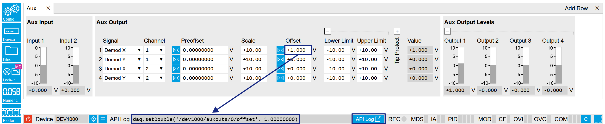
In the LabOne User Interface
A convenient method to learn which node is responsible for a specific
instrument setting is to check the Command Log history in the bottom of
the LabOne User Interface. The command in the Status Bar gets updated
every time a configuration change is made. Figure 1 shows how the equivalent MATLAB
command is displayed after modifying the value of the auxiliary output
1’s offset. The format of the LabOne UI’s command history can be
configured in the Config Tab (MATLAB, Python and .NET are available).
The entire history generated in the current UI session can be viewed by
clicking the "Show Log" button.
Figure 1: When a device’s configuration is modified in the LabOne User Interface, the Status Bar displays the equivalent command to perform the same configuration via a LabOne programming interface. Here, the MATLAB code to modify auxiliary output 1’s offset value is provided. When "Show Log" is clicked the entire configuration history is displayed in a new browser tab.
In a LabOne Programming Interface
A list of nodes (under a specific branch) can be requested from the Data
Server in an API client using the listNodes command (MATLAB, Python,
.NET) or ziAPIListNodes() function (C API). Please see each API’s
command reference for more help using the listNodes command. To obtain
a list of all the nodes that provide data from an instrument at a high
rate, so-called streaming nodes, the streamingonly flag can be
provided to listNodes. More information on data streaming and
streaming nodes is available in the LabOne Programming Manual.
The detailed descriptions of nodes that is provided in
Reference Node Documentation is accessible directly in the LabOne MATLAB or Python
programming interfaces using the "help" command. The help command is
daq.help(path) in Python and ziDAQ('help', path) in MATLAB. The
command returns a description of the instrument node including access
properties, data type, units and available options. The "help" command
also handles wildcards to return a detailed description of all nodes
matching the path. An example is provided below.
daq = zhinst . core . ziDAQServer ( 'localhost' , 8004 , 6 )
daq . help ( '/dev2006/auxouts/0/offset' )
# Out:
# /dev1000/auxouts/0/offset#
# Add the specified offset voltage to the signal after scaling. Auxiliary Output
# Value = (Signal+Preoffset)*Scale + Offset
# Properties: Read, Write, Setting
# Type: Double
# Unit: V
Data Server Nodes
The Data Server has nodes in the node tree available under the top-level
/ZI/ branch. These nodes give information about the version and state of
the Data Server the client is connected to. For example, the nodes:
/ZI/ABOUT/VERSION
/ZI/ABOUT/REVISION
are read-only nodes that contain information about the release version
and revision of the Data Server. The nodes under the /ZI/DEVICES/ list
which devices are connected, discoverable and visible to the Data
Server.
The nodes:
/ZI/CONFIG/OPEN
/ZI/CONFIG/PORT
are settings nodes that can be used to configure which port the Data
Server listens to for incoming client connections and whether it may
accept connections from clients on hosts other than the localhost.
Nodes that are of particular use to programmers are:
/ZI/DEBUG/LOGPATH - the location of the Data Server’s log in the PC’s
file system,
/ZI/DEBUG/LEVEL - the current log-level of the Data Server
(configurable; has the Write attribute),
/ZI/DEBUG/LOG - the last Data Server log entries as a string array.
The Global nodes of the LabOne Data Server are listed in the Instrument Communication
chapter of the LabOne Programming Manual
Reference Node Documentation
This section describes all the nodes in the data server’s node tree organized by branch.
AUCARTS
/dev..../aucarts/n/enable
Properties: Read, Write, Setting
Type: Integer (enumerated)
Unit: None
Enables the streaming of results to the host computer.
0
"on": ON: The arithmetic unit is operative and results are streamed to the host computer.
1
"off": OFF: The arithmetic unit is operative but results are not streamed to the host computer.
/dev..../aucarts/n/mode
Properties: Read, Write, Setting
Type: Integer (enumerated)
Unit: None
Selects the operation mode of the arithmetic unit
0
"add": Add: The arithmetic unit is in add mode: two independent demodulator outputs can be added together.
1
"divide": Divide: The arithmetic unit is in divide mode: two independent demodulator outputs can be divided by each other.
2
"multiply": Multiply: The arithmetic unit is in multiply mode: two independent demodulator outputs can be multiplied with each other.
/dev..../aucarts/n/ops/n/coeff
Properties: Read, Write, Setting
Type: Integer (enumerated)
Unit: None
Select a coefficient to be applied to the selected Signal. Default: 0.
0
"mult_by_1": A coefficient of 1 is used (default).
1
"auxin0", "auxiliary_input0": The signal on Aux In 1 is used as coefficient.
2
"auxin1", "auxiliary_input1": The signal on Aux In 2 is used as coefficient.
3
"cartesian_au0": Output of Cartesian AU 1 (C1) is used as coefficient (for Cartesian AU only).
4
"cartesian_au1": Output of Cartesian AU 2 (C2) is used as coefficient (for Cartesian AU only).
5
"polar_au0": Output of Polar AU 1 (P1) is used as coefficient (for Polar AU only).
6
"polar_au1": Output of Polar AU 2 (P2) is used as coefficient (for Polar AU only).
/dev..../aucarts/n/ops/n/demodselect
Properties: Read, Write, Setting
Type: Integer (64 bit)
Unit: None
Select demodulator and/or Boxcar channel number.
/dev..../aucarts/n/ops/n/scale
Properties: Read, Write, Setting
Type: Double
Unit: None
Custom scaling factor.
/dev..../aucarts/n/ops/n/value
Properties: Read, Write, Setting
Type: Integer (enumerated)
Unit: None
Select the arithmetic unit input signal.
0
"demod_x": Use demodulator X (for Cartesian AU only).
1
"demod_y": Use demodulator Y (for Cartesian AU only).
2
"boxcar": Use Boxcar (for Cartesian AU only).
3
"demod_r": Use demodulator R (for polar AU only).
4
"demod_theta": Use demodulator Θ (for polar AU only).
5
"magnitude": Use the magnitude of C1 + iC2 (for polar AU only).
6
"angle": Use the angle of C1 + iC2 (for polar AU only).
/dev..../aucarts/n/rate
Properties: Read, Write, Setting
Type: Double
Unit: 1/s
Defines the number of arithmetic unit result samples that are sent to the host computer per second.
/dev..../aucarts/n/sample
Properties: Read, Stream
Type: Double
Unit: Dependent
Streaming node giving the output samples of the arithmetic unit.
/dev..../aucarts/n/value
Properties: Read
Type: Double
Unit: Dependent
Gives the result of the arithmetic unit at a low sampling rate (10 per second).
AUPOLARS
/dev..../aupolars/n/enable
Properties: Read, Write, Setting
Type: Integer (64 bit)
Unit: None
Enables the streaming of results to the host computer.
/dev..../aupolars/n/mode
Properties: Read, Write, Setting
Type: Integer (enumerated)
Unit: None
Selects the operation mode of the arithmetic unit.
0
"add": Add: The arithmetic unit is in add mode: two independent demodulator outputs can be added together.
1
"divide": Divide: The arithmetic unit is in divide mode: two independent demodulator outputs can be divided by each other.
2
"multiply": Multiply: The arithmetic unit is in multiply mode: two independent demodulator outputs can be multiplied with each other.
/dev..../aupolars/n/ops/n/coeff
Properties: Read, Write, Setting
Type: Integer (enumerated)
Unit: None
Select a coefficient to be applied to the selected Signal. Default: 0.
0
"mult_by_1": A coefficient of 1 is used (default).
1
"auxin0", "auxiliary_input0": The signal on Aux In 1 is used as coefficient.
2
"auxin1", "auxiliary_input1": The signal on Aux In 2 is used as coefficient.
3
"cartesian_au0": Output of Cartesian AU 1 (C1) is used as coefficient (for Cartesian AU only).
4
"cartesian_au1": Output of Cartesian AU 2 (C2) is used as coefficient (for Cartesian AU only).
5
"polar_au0": Output of Polar AU 1 (P1) is used as coefficient (for Polar AU only).
6
"polar_au1": Output of Polar AU 2 (P2) is used as coefficient (for Polar AU only).
/dev..../aupolars/n/ops/n/demodselect
Properties: Read, Write, Setting
Type: Integer (64 bit)
Unit: None
Select demodulator channel number.
/dev..../aupolars/n/ops/n/scale
Properties: Read, Write, Setting
Type: Double
Unit: None
Custom scaling factor.
/dev..../aupolars/n/ops/n/value
Properties: Read, Write, Setting
Type: Integer (enumerated)
Unit: None
Select the arithmetic unit input signal
0
"demod_x": Use demodulator X (for Cartesian AU only).
1
"demod_y": Use demodulator Y (for Cartesian AU only).
2
"boxcar": Use Boxcar (for Cartesian AU only).
3
"demod_r": Use demodulator R (for polar AU only).
4
"demod_theta": Use demodulator Θ (for polar AU only).
5
"magnitude": Use the magnitude of C1 + iC2 (for polar AU only).
6
"angle": Use the angle of C1 + iC2 (for polar AU only).
/dev..../aupolars/n/rate
Properties: Read, Write, Setting
Type: Double
Unit: 1/s
Defines the number of arithmetic unit result samples that are sent to the host computer per second.
/dev..../aupolars/n/sample
Properties: Read, Stream
Type: Double
Unit: Dependent
Streaming node giving the output samples of the arithmetic unit.
/dev..../aupolars/n/value
Properties: Read
Type: Double
Unit: Dependent
Gives the result of the arithmetic unit at a low sampling rate (10 per second).
AUXINS
/dev..../auxins/n/averaging
Properties: Read, Write, Setting
Type: Integer (64 bit)
Unit: None
Defines the number of samples on the input to average as a power of two. Possible values are in the range [0, 16]. A value of 0 corresponds to the sampling rate of the auxiliary input's ADC.
/dev..../auxins/n/sample
Properties: Read, Stream
Type: ZIAuxInSample
Unit: V
Voltage measured at the Auxiliary Input after averaging. The data rate depends on the averaging value. Note, if the instrument has demodulator functionality, the auxiliary input values are available as fields in a demodulator sample and are aligned by timestamp with the demodulator output.
/dev..../auxins/n/values/n
Properties: Read
Type: Double
Unit: V
Voltage measured at the Auxiliary Input after averaging. The value of this node is updated at a low rate (50 Hz); the streaming node auxins/n/sample is updated at a high rate defined by the averaging.
AUXOUTS
/dev..../auxouts/n/demodselect
Properties: Read, Write, Setting
Type: Integer (64 bit)
Unit: None
Select the channel number of the selected signal source.
/dev..../auxouts/n/limitlower
Properties: Read, Write, Setting
Type: Double
Unit: V
Lower limit for the signal at the Auxiliary Output. A smaller value will be clipped.
/dev..../auxouts/n/limitupper
Properties: Read, Write, Setting
Type: Double
Unit: V
Upper limit for the signal at the Auxiliary Output. A larger value will be clipped.
/dev..../auxouts/n/offset
Properties: Read, Write, Setting
Type: Double
Unit: V
Add the specified offset voltage to the signal after scaling. Auxiliary Output Value = (Signal+Preoffset)*Scale + Offset
/dev..../auxouts/n/outputselect
Properties: Read, Write, Setting
Type: Integer (enumerated)
Unit: None
Select the signal source to be represented on the Auxiliary Output.
-1
"manual": Select Manual as the output option.
0
"demod_x": Select Demod X as the output option.
1
"demod_y": Select Demod Y as the output option.
2
"demod_r": Select Demod R as the output option.
3
"demod_theta": Select Demod Theta as the output option.
4
"awg": Select one of the AWG Outputs for auxiliary output when running the AWG in four-channel mode. The AWG option needs to be installed.
5
"pid", "pid_out": Select PID Out as the output option.
6
"boxcar": Select Boxcar as the output option.
7
"au_cartesian": Select AU Cartesian as the output option.
8
"au_polar": Select AU Polar as the output option.
9
"pid_shift": Select PID Shift as the output option.
10
"pid_error": Select PID Error as the output option.
12
"pulse_counter": Select Pulse Counter as the output option.
/dev..../auxouts/n/preoffset
Properties: Read, Write, Setting
Type: Double
Unit: Dependent
Add a pre-offset to the signal before scaling is applied. Auxiliary Output Value = (Signal+Preoffset)*Scale + Offset
/dev..../auxouts/n/scale
Properties: Read, Write, Setting
Type: Double
Unit: None
Multiplication factor to scale the signal. Auxiliary Output Value = (Signal+Preoffset)*Scale + Offset
/dev..../auxouts/n/value
Properties: Read
Type: Double
Unit: V
Voltage present on the Auxiliary Output. Auxiliary Output Value = (Signal+Preoffset)*Scale + Offset
AWGS
/dev..../awgs/n/auxtriggers/n/channel
Properties: Read, Write, Setting
Type: Integer (enumerated)
Unit: None
Selects the digital trigger source signal.
0
"trigin0", "trigger_input0": Trigger In 1
1
"trigin1", "trigger_input1": Trigger In 2
2
"trigin2", "trigger_input2": Trigger In 3
3
"trigin3", "trigger_input3": Trigger In 4
4
"trigout0", "trigger_output0": Trigger Out 1
5
"trigout1", "trigger_output1": Trigger Out 2
6
"trigout2", "trigger_output2": Trigger Out 3
7
"trigout3", "trigger_output3": Trigger Out 4
/dev..../awgs/n/auxtriggers/n/slope
Properties: Read, Write, Setting
Type: Integer (enumerated)
Unit: None
Select the signal edge that should activate the trigger. The trigger will be level sensitive when the Level option is selected.
0
"level_sensitive": Level sensitive trigger
1
"rising_edge": Rising edge trigger
2
"falling_edge": Falling edge trigger
3
"both_edges": Rising or falling edge trigger
/dev..../awgs/n/auxtriggers/n/state
Properties: Read
Type: Integer (64 bit)
Unit: None
State of the Auxiliary Trigger: No trigger detected/trigger detected.
/dev..../awgs/n/dio/delay/index
Properties: Read, Write, Setting
Type: Integer (64 bit)
Unit: None
Index of the bit on the DIO interface for which the delay should be changed.
/dev..../awgs/n/dio/delay/value
Properties: Read, Write, Setting
Type: Integer (64 bit)
Unit: None
Corresponding delay value to apply to the given bit of the DIO interface in units of 450 MHz clock cycles. Valid values are 0 to 3.
/dev..../awgs/n/dio/strobe/index
Properties: Read, Write, Setting
Type: Integer (64 bit)
Unit: None
Select the DIO bit to use as the STROBE signal.
/dev..../awgs/n/dio/strobe/slope
Properties: Read, Write, Setting
Type: Integer (enumerated)
Unit: None
Select the signal edge of the STROBE signal for use in timing alignment.
0
"off": Off
1
"rising_edge": Rising edge trigger
2
"falling_edge": Falling edge trigger
3
"both_edges": Rising or falling edge trigger
/dev..../awgs/n/dio/valid/index
Properties: Read, Write, Setting
Type: Integer (64 bit)
Unit: None
Select the DIO bit to use as the VALID signal to indicate a valid input is available.
/dev..../awgs/n/dio/valid/polarity
Properties: Read, Write, Setting
Type: Integer (enumerated)
Unit: None
Polarity of the VALID bit that indicates that a valid input is available.
0
"none": None: VALID bit is ignored.
1
"low": Low: VALID bit must be logical zero.
2
"high": High: VALID bit must be logical high.
3
"both": Both: VALID bit may be logical high or zero.
/dev..../awgs/n/elf/checksum
Properties: Read
Type: Integer (64 bit)
Unit: None
Checksum of the uploaded ELF file.
/dev..../awgs/n/elf/data
Properties: Write
Type: ZIVectorData
Unit: None
Accepts the data of the sequencer ELF file.
/dev..../awgs/n/elf/length
Properties: Read
Type: Integer (64 bit)
Unit: None
Length of the compiled ELF file.
/dev..../awgs/n/elf/memoryusage
Properties: Read
Type: Double
Unit: None
Size of the uploaded ELF file relative to the size of the main memory.
/dev..../awgs/n/elf/name
Properties: Read
Type: ZIVectorData
Unit: None
The name of the uploaded ELF file.
/dev..../awgs/n/elf/progress
Properties: Read
Type: Double
Unit: %
The percentage of the sequencer program already uploaded to the device.
/dev..../awgs/n/enable
Properties: Read, Write, Setting
Type: Integer (64 bit)
Unit: None
Activates the AWG.
/dev..../awgs/n/outputs/n/amplitude
Properties: Read, Write, Setting
Type: Double
Unit: None
Amplitude in units of full scale of the given AWG Output. The full scale corresponds to the Range voltage setting of the Signal Outputs.
/dev..../awgs/n/outputs/n/enables/n
Properties: Read
Type: Integer (64 bit)
Unit: None
Indicates the routing of the AWG signal (k index) to the wave output or to the digital mixer input (m index).
/dev..../awgs/n/outputs/n/mode
Properties: Read, Write, Setting
Type: Integer (enumerated)
Unit: None
Select between plain mode, amplitude modulation, and advanced mode.
0
"plain": Plain: AWG Output goes directly to Signal Output.
1
"modulation": Modulation: AWG Output 1 (2) is multiplied with oscillator signal of demodulator 4 (8).
2
"advanced": Advanced: Output of AWG channel 1 (2) modulates demodulators 1-4 (5-8) with independent envelopes.
/dev..../awgs/n/ready
Properties: Read
Type: Integer (64 bit)
Unit: None
AWG has a compiled wave form and is ready to be enabled.
/dev..../awgs/n/sequencer/assembly
Properties: Read
Type: ZIVectorData
Unit: None
Displays the current sequence program in compiled form. Every line corresponds to one hardware instruction.
/dev..../awgs/n/sequencer/memoryusage
Properties: Read
Type: Double
Unit: None
Size of the current Sequencer program relative to the available instruction memory of 1 kInstructions (1'024 instructions).
/dev..../awgs/n/sequencer/pc
Properties: Read
Type: Integer (64 bit)
Unit: None
Current position in the list of sequence instructions during execution.
/dev..../awgs/n/sequencer/program
Properties: Read
Type: ZIVectorData
Unit: None
Displays the source code of the current sequence program.
/dev..../awgs/n/sequencer/status
Properties: Read
Type: Integer (64 bit)
Unit: None
Status of the sequencer on the instrument. Bit 0: sequencer is running; Bit 1: reserved; Bit 2: sequencer is waiting for a trigger to arrive; Bit 3: sequencer is not ready; Bit 4: sequencer is waiting for synchronization with other channels.
/dev..../awgs/n/single
Properties: Read, Write, Setting
Type: Integer (64 bit)
Unit: None
Puts the AWG into single shot mode.
/dev..../awgs/n/sweep/awgtrigs/n
Properties: Read, Write
Type: Double
Unit: Dependent
Node used by the sweeper module for fast index sweeps. When selected as sweep grid the sweeper module will switch into a fast index based scan mode. This mode can be up to 1000 times faster than conventional node sweeps. The sequencer program must support this functionality. See section 'AWG Index Sweep' of the UHF user manual for more information.
/dev..../awgs/n/time
Properties: Read, Write, Setting
Type: Integer (enumerated)
Unit: None
AWG sampling rate. The numeric values are rounded for display purposes. The exact values are equal to the base sampling rate (1.8 GHz) divided by 2^n, where n is the node value. This value is used by default and can be overridden in the Sequence program.
0
"1.80_GHz": 1.80 GHz
1
"900_MHz": 900 MHz
2
"450_MHz": 450 MHz
3
"225_MHz": 225 MHz
4
"113_MHz": 112.5 MHz
5
"56.3_MHz": 56.25 MHz
6
"28.1_MHz": 28.12 MHz
7
"14.1_MHz": 14.06 MHz
8
"7.03_MHz": 7.03 MHz
9
"3.52_MHz": 3.52 MHz
10
"1.76M_Hz": 1.76 MHz
11
"878.91_kHz": 878.91 kHz
12
"439_kHz": 439.45 kHz
13
"220_kHz": 219.73 kHz
/dev..../awgs/n/triggers/n/channel
Properties: Read, Write, Setting
Type: Integer (enumerated)
Unit: None
Selects the signal source for the analogue trigger.
0
"sigin0", "signal_input0": Signal Input 1
1
"sigin1", "signal_input1": Signal Input 2
2
"trigin0", "trigger_input0": Trigger Input 1
3
"trigin1", "trigger_input1": Trigger Input 2
4
"auxout0", "auxiliary_output0": Aux Output 1. Requires an installed digitizer (DIG) option.
5
"auxout1", "auxiliary_output1": Aux Output 2. Requires an installed digitizer (DIG) option.
6
"auxout2", "auxiliary_output2": Aux Output 3. Requires an installed digitizer (DIG) option.
7
"auxout3", "auxiliary_output3": Aux Output 4. Requires an installed digitizer (DIG) option.
8
"auxin0", "auxiliary_input0": Aux Input 1
9
"auxin1", "auxiliary_input1": Aux Input 2
10
"demod3": Osc φ Demod 4
11
"demod7": Osc φ Demod 8
16
"demod0_x": Demod 1 X. Requires an installed digitizer (DIG) option.
17
"demod1_x": Demod 2 X. Requires an installed digitizer (DIG) option.
18
"demod2_x": Demod 3 X. Requires an installed digitizer (DIG) option.
19
"demod3_x": Demod 4 X. Requires an installed digitizer (DIG) option.
20
"demod4_x": Demod 5 X. Requires an installed digitizer (DIG) option.
21
"demod5_x": Demod 6 X. Requires an installed digitizer (DIG) option.
22
"demod6_x": Demod 7 X. Requires an installed digitizer (DIG) option.
23
"demod7_x": Demod 8 X. Requires an installed digitizer (DIG) option.
32
"demod0_y": Demod 1 Y. Requires an installed digitizer (DIG) option.
33
"demod1_y": Demod 2 Y. Requires an installed digitizer (DIG) option.
34
"demod2_y": Demod 3 Y. Requires an installed digitizer (DIG) option.
35
"demod3_y": Demod 4 Y. Requires an installed digitizer (DIG) option.
36
"demod4_y": Demod 5 Y. Requires an installed digitizer (DIG) option.
37
"demod5_y": Demod 6 Y. Requires an installed digitizer (DIG) option.
38
"demod6_y": Demod 7 Y. Requires an installed digitizer (DIG) option.
39
"demod7_y": Demod 8 Y. Requires an installed digitizer (DIG) option.
48
"demod0_r": Demod 1 R. Requires an installed digitizer (DIG) option.
49
"demod1_r": Demod 2 R. Requires an installed digitizer (DIG) option.
50
"demod2_r": Demod 3 R. Requires an installed digitizer (DIG) option.
51
"demod3_r": Demod 4 R. Requires an installed digitizer (DIG) option.
52
"demod4_r": Demod 5 R. Requires an installed digitizer (DIG) option.
53
"demod5_r": Demod 6 R. Requires an installed digitizer (DIG) option.
54
"demod6_r": Demod 7 R. Requires an installed digitizer (DIG) option.
55
"demod7_r": Demod 8 R. Requires an installed digitizer (DIG) option.
64
"demod0_theta": Demod 1 Θ. Requires an installed digitizer (DIG) option.
65
"demod1_theta": Demod 2 Θ. Requires an installed digitizer (DIG) option.
66
"demod2_theta": Demod 3 Θ. Requires an installed digitizer (DIG) option.
67
"demod3_theta": Demod 4 Θ. Requires an installed digitizer (DIG) option.
68
"demod4_theta": Demod 5 Θ. Requires an installed digitizer (DIG) option.
69
"demod5_theta": Demod 6 Θ. Requires an installed digitizer (DIG) option.
70
"demod6_theta": Demod 7 Θ. Requires an installed digitizer (DIG) option.
71
"demod7_theta": Demod 8 Θ. Requires an installed digitizer (DIG) option.
80
"pid0_value": PID 1 value. Requires an installed digitizer (DIG) option.
81
"pid1_value": PID 2 value. Requires an installed digitizer (DIG) option.
82
"pid2_value": PID 3 value. Requires an installed digitizer (DIG) option.
83
"pid3_value": PID 4 value. Requires an installed digitizer (DIG) option.
96
"boxcar0": Boxcar 1. Requires an installed digitizer (DIG) option.
97
"boxcar1": Boxcar 2. Requires an installed digitizer (DIG) option.
112
"au_cartesian0": AU Cartesian 1. Requires an installed digitizer (DIG) option.
113
"au_cartesian1": AU Cartesian 2. Requires an installed digitizer (DIG) option.
128
"au_polar0": AU Polar 1. Requires an installed digitizer (DIG) option.
129
"au_polar1": Au Polar 2. Requires an installed digitizer (DIG) option.
144
"pid0_shift": PID 1 Shift. Requires an installed digitizer (DIG) option.
145
"pid1_shift": PID 2 Shift. Requires an installed digitizer (DIG) option.
146
"pid2_shift": PID 3 Shift. Requires an installed digitizer (DIG) option.
147
"pid3_shift": PID 4 Shift. Requires an installed digitizer (DIG) option.
176
"awg_marker0": AWG Marker 1. Requires an installed digitizer (DIG) option.
177
"awg_marker1": AWG Marker 2. Requires an installed digitizer (DIG) option.
178
"awg_marker2": AWG Marker 3. Requires an installed digitizer (DIG) option.
179
"awg_marker3": AWG Marker 4. Requires an installed digitizer (DIG) option.
192
"awg_trigger0": AWG Trigger 1. Requires an installed digitizer (DIG) option.
193
"awg_trigger1": AWG Trigger 2. Requires an installed digitizer (DIG) option.
194
"awg_trigger2": AWG Trigger 3. Requires an installed digitizer (DIG) option.
195
"awg_trigger3": AWG Trigger 4. Requires an installed digitizer (DIG) option.
208
"pid0_error": PID 1 Error. Requires an installed digitizer (DIG) option.
209
"pid1_error": PID 2 Error. Requires an installed digitizer (DIG) option.
210
"pid2_error": PID 3 Error. Requires an installed digitizer (DIG) option.
211
"pid3_error": PID 4 Error. Requires an installed digitizer (DIG) option.
/dev..../awgs/n/triggers/n/falling
Properties: Read, Write, Setting
Type: Integer (64 bit)
Unit: None
Sets a falling edge trigger.
/dev..../awgs/n/triggers/n/force
Properties: Read, Write, Setting
Type: Integer (64 bit)
Unit: None
Allows to manually force a trigger.
/dev..../awgs/n/triggers/n/gate/enable
Properties: Read, Write, Setting
Type: Integer (64 bit)
Unit: None
If enabled the trigger will be gated by the trigger gating input signal.
/dev..../awgs/n/triggers/n/gate/inputselect
Properties: Read, Write, Setting
Type: Integer (enumerated)
Unit: None
Select the signal source used for trigger gating if gating is enabled.
0
"trigin2", "trigger_input2": Trigger In 3
1
"trigin3", "trigger_input3": Trigger In 4
/dev..../awgs/n/triggers/n/hysteresis/absolute
Properties: Read, Write, Setting
Type: Double
Unit: V
Defines the voltage the source signal must deviate from the trigger level before the trigger is rearmed again. Set to 0 to turn it off. The sign is defined by the Edge setting.
/dev..../awgs/n/triggers/n/hysteresis/mode
Properties: Read, Write, Setting
Type: Integer (enumerated)
Unit: None
Selects the mode to define the hysteresis strength. The relative mode will work best over the full input range as long as the analog input signal does not suffer from excessive noise.
0
"absolute": Selects absolute hysteresis (V).
1
"relative": Selects a hysteresis relative to the adjusted full scale signal input range (%).
/dev..../awgs/n/triggers/n/hysteresis/relative
Properties: Read, Write, Setting
Type: Double
Unit: %
Hysteresis relative to the adjusted full scale signal input range. A hysteresis value larger than 100% is allowed.
/dev..../awgs/n/triggers/n/level
Properties: Read, Write, Setting
Type: Double
Unit: V
Defines the analog trigger level.
/dev..../awgs/n/triggers/n/rising
Properties: Read, Write, Setting
Type: Integer (64 bit)
Unit: None
Sets a rising edge trigger.
/dev..../awgs/n/triggers/n/slope
Properties: Read, Write, Setting
Type: Integer (enumerated)
Unit: None
Select the signal edge that should activate the trigger. The trigger will be level sensitive when the Level option is selected.
0
"level_sensitive": Level sensitive trigger
1
"rising_edge": Rising edge trigger
2
"falling_edge": Falling edge trigger
3
"both_edegs": Rising or falling edge trigger
/dev..../awgs/n/triggers/n/state
Properties: Read
Type: Integer (64 bit)
Unit: None
State of the Trigger: No trigger detected/trigger detected.
/dev..../awgs/n/userregs/n
Properties: Read, Write, Setting
Type: Integer (64 bit)
Unit: None
Integer user register value. The sequencer has reading and writing access to the user register values during run time.
/dev..../awgs/n/waveform/descriptors
Properties: Read
Type: ZIVectorData
Unit: None
JSON-formatted string containing a dictionary of various properties of the current waveform: name, filename, function, channels, marker bits, length, timestamp.
/dev..../awgs/n/waveform/memoryusage
Properties: Read
Type: Double
Unit: %
Amount of the used waveform data relative to the device cache memory. The cache memory provides space for 32 kSa (32'768 Sa) per-channel of waveform data. Memory Usage over 100% means that waveforms must be loaded from the main memory of 64 MSa (67'108'864 Sa) per-channel during playback, which can lead to delays.
/dev..../awgs/n/waveform/waves/n
Properties: Read, Write
Type: ZIVectorData
Unit: None
The waveform data in the instrument's native format for the given playWave waveform index. This node will not work with subscribe as it does not push updates. For short vectors get may be used. For long vectors (causing get to time out) getAsEvent and poll can be used. The index of the waveform to be replaced can be determined using the Waveform sub-tab in the AWG tab of the LabOne User Interface.
BOXCARS
/dev..../boxcars/n/averagerbandwidth 
Properties: Read
Type: Double
Unit: Hz
The 3 dB signal bandwidth of the Boxcar Averager is determined by the oscillation frequency and the Number of Averaging Periods set. Note: internally the boxcar signal is sampled at a rate of 14 MSa/s and the signal bandwidth of the auxiliary output is 7 MHz.
/dev..../boxcars/n/baseline/enable
Properties: Read, Write, Setting
Type: Integer (64 bit)
Unit: None
Enable Baseline Suppression.
/dev..../boxcars/n/baseline/windowstart
Properties: Read, Write, Setting
Type: Double
Unit: degree
Boxcar baseline suppression gate opening start in degrees based on one oscillator frequency period equals 360 degrees.
/dev..../boxcars/n/decimation
Properties: Read
Type: Integer (64 bit)
Unit: None
Indicates, in powers of 2, the number of averager outputs sent to the PC while Averaging Periods Boxcar integrations are obtained. Positive integer values indicate oversampling. Negative integer values indicate undersampling. Examples for oversampling values: 0 : 2^0 = 1 averager output is sent to the PC during Averaging Periods Boxcar integrations. 2 : 2^2 = 4 averager outputs are sent to the PC during Averaging Periods Boxcar integrations. -1 : 2^-1 = 0.5, only every other Averaging Periods Boxcar integrations an averager output is sent to the PC.
/dev..../boxcars/n/enable
Properties: Read, Write, Setting
Type: Integer (64 bit)
Unit: Dependent
Enable the BOXCAR unit.
/dev..../boxcars/n/fifooverflow
Properties: Read
Type: Integer (64 bit)
Unit: None
Data lost during streaming to PC. Sticky flag cleared by restarting the boxcar.
/dev..../boxcars/n/freqoverflow
Properties: Read
Type: Integer (64 bit)
Unit: None
Frequency for the boxcar is above or equal 450 MHz. The boxcar output may not be reliable any more. Sticky flag cleared by restarting the boxcar.
/dev..../boxcars/n/inputselect
Properties: Read, Write, Setting
Type: Integer (enumerated)
Unit: None
Select Signal Input used for the boxcar analysis.
0
"sigin0", "signal_input0": Sig In 1
1
"sigin1", "signal_input1": Sig In 2
/dev..../boxcars/n/limitrate
Properties: Read, Write, Setting
Type: Double
Unit: 1/s
Rate Limit for Boxcar output data sent to PC. This value does not affect the Aux Output for which the effective rate is given by min(14 MSa/s , Frequency / max(1, Averaging Periods/512)).
/dev..../boxcars/n/oscselect
Properties: Read, Write, Setting
Type: Integer (enumerated)
Unit: None
Selection of the oscillator used for the boxcar analysis.
0
Oscillator 1
1
Oscillator 2
2
Oscillator 3
3
Oscillator 4
4
Oscillator 5
5
Oscillator 6
6
Oscillator 7
7
Oscillator 8
/dev..../boxcars/n/overflow
Properties: Read
Type: Integer (64 bit)
Unit: None
Overflow detected. The boxcar output may not be reliable any more. Sticky flag cleared by restarting the boxcar.
/dev..../boxcars/n/periodoverflowevents
Properties: Read
Type: Integer (64 bit)
Unit: None
The boxcar averaging gate opening width is more than one cycle of the signal and should be reduced.
/dev..../boxcars/n/periods
Properties: Read, Write, Setting
Type: Integer (64 bit)
Unit: None
Number of periods to average. This setting has no effect on Output PWAs.
/dev..../boxcars/n/rate
Properties: Read
Type: Double
Unit: 1/s
Current data transfer rate to the PC given by min(14 MSa/s , Frequency / max(1, Averaging Periods/512)). This value is read-only.
/dev..../boxcars/n/sample
Properties: Read, Stream
Type: Double
Unit: V
Streaming node containing the output data of the boxcar.
/dev..../boxcars/n/value
Properties: Read
Type: Double
Unit: Dependent
The current boxcar output.
/dev..../boxcars/n/windowsize
Properties: Read, Write, Setting
Type: Double
Unit: s
Boxcar averaging gate opening width in seconds. It can be converted to phase assuming 360 equals to a full period of the driving oscillator.
/dev..../boxcars/n/windowstart
Properties: Read, Write, Setting
Type: Double
Unit: degree
Boxcar averaging gate opening start in degrees. It can be converted to time assuming 360 equals to a full period of the driving oscillator.
CLOCKBASE
/dev..../clockbase
Properties: Read
Type: Double
Unit: Hz
Returns the internal clock frequency of the device.
CNTS
/dev..../cnts/n/enable
Properties: Read, Write, Setting
Type: Integer (64 bit)
Unit: None
Enable the pulse counter unit.
/dev..../cnts/n/gateselect
Properties: Read, Write, Setting
Type: Integer (enumerated)
Unit: None
Select the signal source used for enabling the counter in the Gated Free Running and Gated modes.
0
"trigin0", "trigger_input0": Trigger/Ref Input 1 (front panel).
1
"trigin1", "trigger_input1": Trigger/Ref Input 2 (front panel).
2
"trigin2", "trigger_input2": Trigger Input 3 (rear panel).
3
"trigin3", "trigger_input3": Trigger Input 4 (rear panel).
4
"awgtrig0", "awg_trigger0": AWG Trigger 1.
5
"awgtrig1", "awg_trigger1": AWG Trigger 2.
6
"awgtrig2", "awg_trigger2": AWG Trigger 3.
7
"awgtrig3", "awg_trigger3": AWG Trigger 4.
/dev..../cnts/n/inputselect
Properties: Read, Write, Setting
Type: Integer (enumerated)
Unit: None
Select the counter signal source.
0
"dio_bit0": DIO Bit 0.
1
"dio_bit1": DIO Bit 1.
2
"dio_bit2": DIO Bit 2.
3
"dio_bit3": DIO Bit 3.
4
"dio_bit4": DIO Bit 4.
5
"dio_bit5": DIO Bit 5.
6
"dio_bit6": DIO Bit 6.
7
"dio_bit7": DIO Bit 7.
8
"dio_bit8": DIO Bit 8.
9
"dio_bit9": DIO Bit 9.
10
"dio_bit10": DIO Bit 10.
11
"dio_bit11": DIO Bit 11.
12
"dio_bit12": DIO Bit 12.
13
"dio_bit13": DIO Bit 13.
14
"dio_bit14": DIO Bit 14.
15
"dio_bit15": DIO Bit 15.
16
"dio_bit16": DIO Bit 16.
17
"dio_bit17": DIO Bit 17.
18
"dio_bit18": DIO Bit 18.
19
"dio_bit19": DIO Bit 19.
20
"dio_bit20": DIO Bit 20.
21
"dio_bit21": DIO Bit 21.
22
"dio_bit22": DIO Bit 22.
23
"dio_bit23": DIO Bit 23.
24
"dio_bit24": DIO Bit 24.
25
"dio_bit25": DIO Bit 25.
26
"dio_bit26": DIO Bit 26.
27
"dio_bit27": DIO Bit 27.
28
"dio_bit28": DIO Bit 28.
29
"dio_bit29": DIO Bit 29.
30
"dio_bit30": DIO Bit 30.
31
"dio_bit31": DIO Bit 31.
32
"trigin0", "trigger_input0": Trigger/Ref Input 1 (front panel).
33
"trigin1", "trigger_input1": Trigger/Ref Input 2 (front panel).
34
"trigin2", "trigger_input2": Trigger Input 3 (rear panel).
35
"trigin3", "trigger_input3": Trigger Input 4 (rear panel).
/dev..../cnts/n/integrate
Properties: Read, Write, Setting
Type: Integer (64 bit)
Unit: None
Sum up counter values over time.
/dev..../cnts/n/mode
Properties: Read, Write, Setting
Type: Integer (enumerated)
Unit: None
Select the run mode of the counter unit.
1
"free_running": Free Running: The counter runs on a repetitive time base defined by the Period field. At the beginning of each period the counter is reset, and at the end, the accumulated number of counts is output.
2
"gated_free_running": Gated Free Running: The counter runs on a repetitive time base defined by the Period field. The Gate Input signal controls when the unit counter is allowed to run. The counter as well as the timer is reset when the Gate Input signal is low. The counter will only deliver new values if the Gate Input signal is high for a time longer than the configured Period.
3
"gated": Gated: The counter is controlled with the Gate Input signal. The counter is enabled at the rising edge of the Gate Input signal and disabled at the falling edge. Pulses are counted as long as the counter is enabled. The accumulated number of counts is output on the falling edge of the Gate Input signal.
4
"time_tagging": Time Tagging: Every pulse is detected individually and tagged with the time of the event. The Period defines the minimum hold-off time between the tagging of two subsequent pulses. If more than one pulse occurs within the window defined by the Period, then the pulses are accumulated and output at the end of the window. The Period effectively determines the maximum rate at which pulse information can be transmitted to the host PC.
/dev..../cnts/n/operation
Properties: Read, Write, Setting
Type: Integer (enumerated)
Unit: None
Select the arithmetic operation (addition, subtraction) applied to the counter unit outputs. 'Other counter' refers to the grouping of the counter units: 1 with 2, and 3 with 4.
0
"none": None
1
"add_other_counter": Add Other Counter
2
"subtract_other_counter": Subtract Other Counter
/dev..../cnts/n/period
Properties: Read, Write, Setting
Type: Double
Unit: s
Set the period used for the Free Running and Gated Free Running modes. Also sets the hold-off time for the Time Tagging mode.
/dev..../cnts/n/sample
Properties: Read, Stream
Type: ZICntSample
Unit: None
Streaming node containing counter values.
/dev..../cnts/n/trigfalling
Properties: Read, Write, Setting
Type: Integer (64 bit)
Unit: None
Performs a trigger event when the source signal crosses the trigger level from high to low. For dual edge triggering, select also the rising edge.
/dev..../cnts/n/trigrising
Properties: Read, Write, Setting
Type: Integer (64 bit)
Unit: None
Performs a trigger event when the source signal crosses the trigger level from low to high. For dual edge triggering, select also the falling edge.
/dev..../cnts/n/value
Properties: Read
Type: Integer (64 bit)
Unit: None
Counter output value.
DEMODS
/dev..../demods/n/adcselect
Properties: Read, Write, Setting
Type: Integer (enumerated)
Unit: None
Selects the input signal for the demodulator.
0
"sigin0", "signal_input0": Sig In 1
1
"sigin1", "signal_input1": Sig In 2
2
"trigin0", "trigger_input0": Trigger Input 1
3
"trigin1", "trigger_input1": Trigger Input 2
4
"auxout0", "auxiliary_output0": Aux Out 1
5
"auxout1", "auxiliary_output1": Aux Out 2
6
"auxout2", "auxiliary_output2": Aux Out 3
7
"auxout3", "auxiliary_output3": Aux Out 4
8
"auxin0", "auxiliary_input0": Aux In 1
9
"auxin1", "auxiliary_input1": Aux In 2
10
"demod3": φ Demod 4
11
"demod7": φ Demod 8
/dev..../demods/n/bypass
Properties: Read, Write, Setting
Type: Integer (64 bit)
Unit: None
Allows to bypass the demodulator low-pass filter, thus increasing the bandwidth.
/dev..../demods/n/enable
Properties: Read, Write, Setting
Type: Integer (enumerated)
Unit: None
Enables the data acquisition for the corresponding demodulator. Note: increasing number of active demodulators increases load on the physical connection to the host computer.
0
"off": OFF: demodulator inactive
1
"on": ON: demodulator active
/dev..../demods/n/freq
Properties: Read
Type: Double
Unit: Hz
Indicates the frequency used for demodulation and for output generation. The demodulation frequency is calculated as oscillator frequency times the harmonic factor. When the MOD option is used linear combinations of oscillator frequencies including the harmonic factors define the sideband frequencies.
/dev..../demods/n/harmonic
Properties: Read, Write, Setting
Type: Integer (64 bit)
Unit: None
Multiplies the selected oscillator's frequency by an integer. If the demodulator is used as a phase detector in external reference mode (PLL), the effect is that the internal oscillator locks to the external frequency divided by the integer factor.
/dev..../demods/n/order
Properties: Read, Write, Setting
Type: Integer (enumerated)
Unit: None
Selects the filter roll off between 6 dB/oct and 48 dB/oct.
1
1st order filter 6 dB/oct
2
2nd order filter 12 dB/oct
3
3rd order filter 18 dB/oct
4
4th order filter 24 dB/oct
5
5th order filter 30 dB/oct
6
6th order filter 36 dB/oct
7
7th order filter 42 dB/oct
8
8th order filter 48 dB/oct
/dev..../demods/n/oscselect
Properties: Read, Write, Setting
Type: Integer (enumerated)
Unit: None
Assignes an oscillator to the demodulator. Number of available oscillators depends on the installed options.
0
Oscillator 1
1
Oscillator 2
2
Oscillator 3
3
Oscillator 4
4
Oscillator 5
5
Oscillator 6
6
Oscillator 7
7
Oscillator 8
/dev..../demods/n/phaseadjust
Properties: Read, Write
Type: Integer (64 bit)
Unit: None
Adjust the demodulator phase automatically in order to read 0 degrees.
/dev..../demods/n/phaseshift
Properties: Read, Write, Setting
Type: Double
Unit: deg
Applies phase shift to the reference input of the demodulator.
/dev..../demods/n/rate
Properties: Read, Write, Setting
Type: Double
Unit: 1/s
Defines the demodulator sampling rate, the number of samples that are sent to the host computer per second. A rate of about 7-10 higher as compared to the filter bandwidth usually provides sufficient aliasing suppression. This is also the rate of data received by LabOne Data Server and saved to the computer hard disk. This setting has no impact on the sample rate on the auxiliary outputs connectors. Note: the value inserted by the user may be approximated to the nearest value supported by the instrument.
/dev..../demods/n/sample
Properties: Read, Stream
Type: ZIDemodSample
Unit: Dependent
Contains streamed demodulator samples with sample interval defined by the demodulator data rate.
/dev..../demods/n/sinc
Properties: Read, Write, Setting
Type: Integer (64 bit)
Unit: None
Enables the sinc filter. When the filter bandwidth is comparable to or larger than the demodulation frequency, the demodulator output may contain frequency components at the frequency of demodulation and its higher harmonics. The sinc is an additional filter that attenuates these unwanted components in the demodulator output.
/dev..../demods/n/timeconstant
Properties: Read, Write, Setting
Type: Double
Unit: s
Sets the integration time constant or in other words, the cutoff frequency of the demodulator low pass filter.
/dev..../demods/n/trigger
Properties: Read, Write, Setting
Type: Integer (enumerated)
Unit: None
Selects the acquisition mode (i.e. triggering) of the demodulator.
0
"continuous": Continuous: demodulator data is continuously streamed to the host computer.
1
"trigin2_rising", "trigger_input2_rising": Trigger Input 3: rising edge triggered.
2
"trigin2_falling", "trigger_input2_falling": Trigger Input 3: falling edge triggered.
3
"trigin2_both", "trigger_input2_both": Trigger Input 3: triggering on both rising and falling edge.
4
"trigin3_rising", "trigger_input3_rising": Trigger Input 4: rising edge triggered.
5
"trigin2or3_rising", "trigger_input2or3_rising": Trigger Input 3 or 4: rising edge triggered on either input.
8
"trigin3_falling", "trigger_input3_falling": Trigger Input 4: falling edge triggered.
10
"trigin2or3_falling", "trigger_input2or3_falling": Trigger Input 3 or 4: falling edge triggered on either input.
12
"trigin3_both", "trigger_input3_both": Trigger Input 4: triggering on both rising and falling edge.
15
"trigin2or3_both", "trigger_input2or3_both": Trigger Input 3 or 4: triggering on both rising and falling edge or either trigger input.
16
"trigin2_low", "trigger_input2_low": Trigger Input 3: demodulator data is streamed to the host computer when the level is low (TTL).
32
"trigin2_high", "trigger_input2_high": Trigger Input 3: demodulator data is streamed to the host computer when the level is high (TTL).
64
"trigin3_low", "trigger_input3_low": Trigger Input 4: demodulator data is streamed to the host computer when the level is low (TTL).
80
"trigin2or3_low", "trigger_input2or3_low": Trigger Input 3 or 4: demodulator data is streamed to the host computer when either level is low (TTL).
128
"trigin3_high", "trigger_input3_high": Trigger Input 4: demodulator data is streamed to the host computer when the level is high (TTL).
160
"trigin2or3_high", "trigger_input2or3_high": Trigger Input 3 or 4: demodulator data is streamed to the host computer when either level is high (TTL).
1048576
"awg_trigger0_rising": AWG Trigger 1: rising edge triggered. Requires an installed AWG option.
2097152
"awg_trigger1_rising": AWG Trigger 2: rising edge triggered. Requires an installed AWG option.
4194304
"awg_trigger2_rising": AWG Trigger 3: rising edge triggered. Requires an installed AWG option.
8388608
"awg_trigger3_rising": AWG Trigger 4: rising edge triggered. Requires an installed AWG option.
16777216
"awg_trigger0_high": AWG Trigger 1: demodulator data is streamed to the host computer when the level is high. Requires an installed AWG option.
33554432
"awg_trigger1_high": AWG Trigger 2: demodulator data is streamed to the host computer when the level is high. Requires an installed AWG option.
67108864
"awg_trigger2_high": AWG Trigger 3: demodulator data is streamed to the host computer when the level is high. Requires an installed AWG option.
134217728
"awg_trigger3_high": AWG Trigger 4: demodulator data is streamed to the host computer when the level is high. Requires an installed AWG option.
DIOS
/dev..../dios/n/auxdrive
Properties: Read
Type: Integer (64 bit)
Unit: None
Not used. Reserved for future use.
/dev..../dios/n/decimation
Properties: Read, Write, Setting
Type: Integer (64 bit)
Unit: None
Sets the decimation factor for DIO data streamed to the host computer.
/dev..../dios/n/drive
Properties: Read, Write, Setting
Type: Integer (64 bit)
Unit: None
When on (1), the corresponding 8-bit bus is in output mode. When off (0), it is in input mode. Bit 0 corresponds to the least significant byte. For example, the value 1 drives the least significant byte, the value 8 drives the most significant byte.
/dev..../dios/n/extclk
Properties: Read, Write, Setting
Type: Integer (enumerated)
Unit: None
Select DIO internal or external clocking.
0
"internal": The DIO is internally clocked with a frequency of 56.25 MHz.
1
"external": The DIO is externally clocked with a clock signal connected to DIO Pin 68. The available range is from 1 Hz up to the internal clock frequency.
/dev..../dios/n/input
Properties: Read, Stream
Type: ZIDIOSample
Unit: None
Gives the value of the DIO input for those bytes where drive is disabled.
/dev..../dios/n/mode
Properties: Read, Write, Setting
Type: Integer (enumerated)
Unit: None
Select DIO mode
0
"manual": Enables manual control of the DIO output bits.
1
"awg_sequencer_commands": Enables setting of DIO output values by AWG sequencer commands.
/dev..../dios/n/output
Properties: Read, Write, Setting
Type: Integer (64 bit)
Unit: None
Sets the value of the DIO output for those bytes where 'drive' is enabled.
EXTREFS
/dev..../extrefs/n/adcselect
Properties: Read, Write, Setting
Type: Integer (enumerated)
Unit: None
Indicates the input signal selection for the selected demodulator.
0
"sigin0", "signal_input0": Signal Input 1 is connected to the corresponding demodulator.
1
"sigin1", "signal_input1": Signal Input 2 is connected to the corresponding demodulator.
2
"trigin0", "trigger_input0": Trigger Input 1 is connected to the corresponding demodulator.
3
"trigin1", "trigger_input1": Trigger Input 2 is connected to the corresponding demodulator.
4
"auxout0", "auxiliary_output0": Auxiliary Output 1 is connected to the corresponding demodulator.
5
"auxout1", "auxiliary_output1": Auxiliary Output 2 is connected to the corresponding demodulator.
6
"auxout2", "auxiliary_output2": Auxiliary Output 3 is connected to the corresponding demodulator.
7
"auxout3", "auxiliary_output3": Auxiliary Output 4 is connected to the corresponding demodulator.
8
"auxin0", "auxiliary_input0": Auxiliary Input 1 is connected to the corresponding demodulator.
9
"auxin1", "auxiliary_input1": Auxiliary Input 2 is connected to the corresponding demodulator.
10
"demod3": Oscillator Phase of Demod 4 is connected to the corresponding demodulator. This selection combined with the demodulator's ExtRef Mode can be used to phase-lock two internal oscillators.
11
"demod7": Oscillator Phase of Demod 8 is connected to the corresponding demodulator. This selection combined with the demodulator's ExtRef Mode can be used to phase-lock two internal oscillators.
/dev..../extrefs/n/automode
Properties: Read, Write, Setting
Type: Integer (enumerated)
Unit: None
This defines the type of automatic adaptation of parameters in the PID used for Ext Ref.
2
"low_bandwidth", "pid_coeffs_filter_low_bw": The PID coefficients, the filter bandwidth and the output limits are automatically set using a low bandwidth.
3
"high_bandwidth", "pid_coeffs_filter_high_bw": The PID coefficients, the filter bandwidth and the output limits are automatically set using a high bandwidth.
4
"all", "pid_coeffs_filter_auto_bw": The PID coefficient, the filter bandwidth and the output limits are dynamically adapted.
/dev..../extrefs/n/demodselect
Properties: Read
Type: Integer (64 bit)
Unit: None
Indicates the demodulator connected to the extref channel.
/dev..../extrefs/n/enable
Properties: Read, Write, Setting
Type: Integer (64 bit)
Unit: None
Enables the external reference.
/dev..../extrefs/n/locked
Properties: Read
Type: Integer (64 bit)
Unit: None
Indicates whether the external reference is locked.
/dev..../extrefs/n/oscselect
Properties: Read
Type: Integer (64 bit)
Unit: None
Indicates which oscillator is being locked to the external reference.
FEATURES
/dev..../features/code
Properties: Write
Type: String
Unit: None
Node providing a mechanism to write feature codes.
/dev..../features/devtype
Properties: Read
Type: String
Unit: None
Returns the device type.
/dev..../features/options
Properties: Read
Type: String
Unit: None
Returns enabled options.
/dev..../features/serial
Properties: Read
Type: String
Unit: None
Device serial number.
/dev..../inputpwas/n/acquisitiontime
Properties: Read
Type: Double
Unit: s
Estimated time needed for recording of the specified number of samples.
/dev..../inputpwas/n/enable
Properties: Read, Write, Setting
Type: Integer (64 bit)
Unit: None
Enables the PWA for data acquisition. Depending on the value of the 'single' node, this may be continuous, or a one-shot acquisition.
/dev..../inputpwas/n/harmonic
Properties: Read, Write, Setting
Type: Integer (64 bit)
Unit: None
Defines the width of the PWA acquisition window in terms of harmonics of the selected reference oscillator frequency. e.g. A value of 1 corresponds to a complete cycle of the reference frequency. A value of 2 corresponds to half of a cycle (180 deg). A value of 4 corresponds to a quarter of a cycle (90 deg).
/dev..../inputpwas/n/holdoff
Properties: Read, Write, Setting
Type: Double
Unit: None
Not used. Reserved for future use.
/dev..../inputpwas/n/inputinterlock
Properties: Read, Write, Setting
Type: Integer (64 bit)
Unit: None
Interlock PWA and Boxcar Input settings. If on, the input signal has to be selected via the boxcar inputselect node.
/dev..../inputpwas/n/inputselect
Properties: Read, Write, Setting
Type: Integer (enumerated)
Unit: None
Select PWA input signal. Has no effect if the inputinterlock node is set active.
0
"sigin0", "signal_input0": Signal Input 1
1
"sigin1", "signal_input1": Signal Input 2
2
"trigin0", "trigger_input0": Trigger 1 (Front)
3
"trigin1", "trigger_input1": Trigger 2 (Front)
4
"auxout0", "auxiliary_output0": Aux Output 1. Requires an installed digitizer (DIG) option.
5
"auxout1", "auxiliary_output1": Aux Output 2. Requires an installed digitizer (DIG) option.
6
"auxout2", "auxiliary_output2": Aux Output 3. Requires an installed digitizer (DIG) option.
7
"auxout3", "auxiliary_output3": Aux Output 4. Requires an installed digitizer (DIG) option.
8
"auxin0", "auxiliary_input0": Aux Input 1
9
"auxin1", "auxiliary_input1": Aux Input 2
10
"demod3": Osc φ Demod 4
11
"demod7": Osc φ Demod 8
/dev..../inputpwas/n/looptime
Properties: Read
Type: Double
Unit: None
Not used. Reserved for future use.
/dev..../inputpwas/n/mode
Properties: Read, Write, Setting
Type: Integer (enumerated)
Unit: None
Sets the data interpretation mode. Measurement data can be interpreted in four different modes and displayed over either phase (native), time, frequency (FFT) or harmonics of the base frequency (FFT).
0
"phase": Phase
1
"time": Time
2
"frequency": Freq Domain (FFT)
3
"harmonics": Harmonics (FFT)
/dev..../inputpwas/n/oscselect
Properties: Read, Write, Setting
Type: Integer (enumerated)
Unit: None
Select reference oscillator for PWA signal acquisition. Has no effect if the inputinterlock node is set active.
0
Oscillator 1
1
Oscillator 2
2
Oscillator 3
3
Oscillator 4
4
Oscillator 5
5
Oscillator 6
6
Oscillator 7
7
Oscillator 8
/dev..../inputpwas/n/progress
Properties: Read
Type: Double
Unit: %
State of the PWA acquisition in percent.
/dev..../inputpwas/n/samplecount
Properties: Read, Write, Setting
Type: Integer (64 bit)
Unit: None
Defines the number of samples acquired of each PWA data set (450 MSa/s).
/dev..../inputpwas/n/shift
Properties: Read, Write, Setting
Type: Double
Unit: degree
Defines the start of the PWA range in terms of the phase of the reference frequency.
/dev..../inputpwas/n/single
Properties: Read, Write, Setting
Type: Integer (64 bit)
Unit: None
If set to 1, a single data acquisition is executed when the PWA is enabled.
/dev..../inputpwas/n/status
Properties: Read
Type: Integer (64 bit)
Unit: None
Indicates whether the PWA is acquiring data. 0 = PWA is inactive, 1 = acquiring data, 2 = terminating acquisition.
/dev..../inputpwas/n/termination
Properties: Read, Write, Setting
Type: Integer (64 bit)
Unit: None
Defines the condition under which an acquisition is prematurely terminated (before acquiring the specified number of samples). Normally has the value 1.
/dev..../inputpwas/n/wave
Properties: Read, Stream
Type: ZIPWAWave
Unit: Dependent
Streaming node that delivers the acquired data from the PWA.
MODS
/dev..../mods/n/carrier/amplitude
Properties: Read, Write, Setting
Type: Double
Unit: V
Set the carrier amplitude
/dev..../mods/n/carrier/enable
Properties: Read, Write, Setting
Type: Integer (64 bit)
Unit: None
Enable the modulation
/dev..../mods/n/carrier/harmonic
Properties: Read, Write, Setting
Type: Integer (64 bit)
Unit: None
Set the harmonic of the carrier frequency. 1 = Fundamental
/dev..../mods/n/carrier/inputselect
Properties: Read, Write, Setting
Type: Integer (enumerated)
Unit: None
Select Signal Input for the carrier demodulation
0
"sigin0", "signal_input0": Sig In 1
1
"sigin1", "signal_input1": Sig In 2
2
"trigin0", "trigger_input0": Trigger Input 1
3
"trigin1", "trigger_input1": Trigger Input 2
4
"auxout0", "auxiliary_output0": Aux Out 1
5
"auxout1", "auxiliary_output1": Aux Out 2
6
"auxout2", "auxiliary_output2": Aux Out 3
7
"auxout3", "auxiliary_output3": Aux Out 4
8
"auxin0", "auxiliary_input0": Aux In 1
9
"auxin1", "auxiliary_input1": Aux In 2
10
"demod3": φ Demod 4
11
"demod7": φ Demod 8
/dev..../mods/n/carrier/order
Properties: Read, Write, Setting
Type: Integer (enumerated)
Unit: None
Selects the filter roll off between 6 dB/oct and 48 dB/oct for carrier demodulation
1
1st order filter 6 dB/oct
2
2nd order filter 12 dB/oct
3
3rd order filter 18 dB/oct
4
4th order filter 24 dB/oct
5
5th order filter 30 dB/oct
6
6th order filter 36 dB/oct
7
7th order filter 42 dB/oct
8
8th order filter 48 dB/oct
/dev..../mods/n/carrier/oscselect
Properties: Read, Write, Setting
Type: Integer (enumerated)
Unit: None
Select the oscillator for the carrier signal.
0
Oscillator 1
1
Oscillator 2
2
Oscillator 3
3
Oscillator 4
4
Oscillator 5
5
Oscillator 6
6
Oscillator 7
7
Oscillator 8
/dev..../mods/n/carrier/phaseadjust
Properties: Read, Write
Type: Integer (64 bit)
Unit: None
Adjust the carrier demodulator phase automatically in order to read 0 degrees.
/dev..../mods/n/carrier/phaseshift
Properties: Read, Write, Setting
Type: Double
Unit: degree
Phase shift applied to the reference input of the carrier demodulator and also to the carrier signal on the Signal Outputs
/dev..../mods/n/carrier/timeconstant
Properties: Read, Write, Setting
Type: Double
Unit: s
Sets the integration time constant or in other words, the cutoff frequency of the low-pass filter for the carrier demodulation.
/dev..../mods/n/enable
Properties: Read, Write, Setting
Type: Integer (64 bit)
Unit: None
Enables the modulation.
/dev..../mods/n/freqdev
Properties: Read, Write, Setting
Type: Double
Unit: Hz
FM mode peak deviation value.
/dev..../mods/n/freqdevenable
Properties: Read, Write, Setting
Type: Integer (enumerated)
Unit: None
In FM mode, choose to work with either modulation index or peak deviation. The modulation index equals peak deviation divided by modulation frequency.
0
"modulation_index": Use modulation index.
1
"peak_deviation": Use peak deviation.
/dev..../mods/n/index
Properties: Read, Write, Setting
Type: Double
Unit: None
FM modulation index: The modulation index equals peak deviation divided by modulation frequency.
/dev..../mods/n/mode
Properties: Read, Write, Setting
Type: Integer (enumerated)
Unit: None
Select the modulation mode.
0
"am": AM Modulation
1
"fm": FM Modulation
2
"manual": Manual
/dev..../mods/n/output
Properties: Read, Write, Setting
Type: Integer (enumerated)
Unit: None
Select Signal Output.
0
"none": None
1
"sigout0", "signal_output0": Signal Output 1
2
"sigout1", "signal_output1": Signal Output 2
3
"sigout0and1", "signal_output0and1": Signal Output 1 and 2
/dev..../mods/n/sidebands/n/amplitude 
Properties: Read, Write, Setting
Type: Double
Unit: V
Set the amplitude of the sideband components.
/dev..../mods/n/sidebands/n/enable 
Properties: Read, Write, Setting
Type: Integer (64 bit)
Unit: None
Enable the signal generation for the respective sideband
/dev..../mods/n/sidebands/n/harmonic 
Properties: Read, Write, Setting
Type: Integer (64 bit)
Unit: None
Set harmonic of the sideband frequencies. 1 = fundamental
/dev..../mods/n/sidebands/n/inputselect 
Properties: Read, Write, Setting
Type: Integer (enumerated)
Unit: None
Select Signal Input for the sideband demodulation
0
"sigin0", "signal_input0": Sig In 1
1
"sigin1", "signal_input1": Sig In 2
2
"trigin0", "trigger_input0": Trigger Input 1
3
"trigin1", "trigger_input1": Trigger Input 2
4
"auxout0", "auxiliary_output0": Aux Out 1
5
"auxout1", "auxiliary_output1": Aux Out 2
6
"auxout2", "auxiliary_output2": Aux Out 3
7
"auxout3", "auxiliary_output3": Aux Out 4
8
"auxin0", "auxiliary_input0": Aux In 1
9
"auxin1", "auxiliary_input1": Aux In 2
10
"demod3": φ Demod 4
11
"demod7": φ Demod 8
/dev..../mods/n/sidebands/n/mode 
Properties: Read, Write, Setting
Type: Integer (enumerated)
Unit: None
Enabling of the first sideband and selection of the position of the sideband relative to the carrier frequency for manual mode.
0
"off": Off: First sideband is disabled. The sideband demodulator behaves like a normal demodulator.
1
"upper": C + M: First sideband to the right of the carrier
2
"lower": C - M: First sideband to the left of the carrier
/dev..../mods/n/sidebands/n/order 
Properties: Read, Write, Setting
Type: Integer (enumerated)
Unit: None
Selects the filter roll off between 6 dB/oct and 48 dB/oct for sideband demodulation
1
1st order filter 6 dB/oct
2
2nd order filter 12 dB/oct
3
3rd order filter 18 dB/oct
4
4th order filter 24 dB/oct
5
5th order filter 30 dB/oct
6
6th order filter 36 dB/oct
7
7th order filter 42 dB/oct
8
8th order filter 48 dB/oct
/dev..../mods/n/sidebands/n/oscselect 
Properties: Read, Write, Setting
Type: Integer (enumerated)
Unit: None
Select the oscillator for the second sideband.
0
Oscillator 1
1
Oscillator 2
2
Oscillator 3
3
Oscillator 4
4
Oscillator 5
5
Oscillator 6
6
Oscillator 7
7
Oscillator 8
/dev..../mods/n/sidebands/n/phaseadjust 
Properties: Read, Write
Type: Integer (64 bit)
Unit: None
Adjust the sideband demodulator phase automatically in order to read 0 degrees.
/dev..../mods/n/sidebands/n/phaseshift 
Properties: Read, Write, Setting
Type: Double
Unit: degree
Phase shift applied to the reference input of the sideband demodulator and also to the sideband signal on the Signal Outputs
/dev..../mods/n/sidebands/n/timeconstant 
Properties: Read, Write, Setting
Type: Double
Unit: s
Sets the integration time constant or in other words, the cutoff frequency of the low-pass filter for the sideband demodulation.
OSCS
/dev..../oscs/n/freq
Properties: Read, Write, Setting
Type: Double
Unit: Hz
Frequency control for each oscillator.
OUTPUTPWAS
/dev..../outputpwas/n/acquisitiontime
Properties: Read
Type: Double
Unit: s
Estimated time needed for recording of the specified number of samples.
/dev..../outputpwas/n/enable
Properties: Read, Write, Setting
Type: Integer (64 bit)
Unit: None
Enables the Output PWA for data acquisition. Depending on the value of the 'single' node, this may be continuous, or a one-shot acquisition.
/dev..../outputpwas/n/harmonic
Properties: Read, Write, Setting
Type: Integer (64 bit)
Unit: None
Defines the width of the PWA acquisition window in terms of harmonics of the selected reference oscillator frequency. e.g. A value of 1 corresponds to a complete cycle of the reference frequency. A value of 2 corresponds to half of a cycle (180 deg). A value of 4 corresponds to a quarter of a cycle (90 deg).
/dev..../outputpwas/n/holdoff
Properties: Read, Write, Setting
Type: Double
Unit: None
Not used. Reserved for future use.
/dev..../outputpwas/n/inputselect
Properties: Read, Write, Setting
Type: Integer (enumerated)
Unit: None
Select PWA input signal.
0
"boxcar0": Boxcar 1
1
"boxcar1": Boxcar 2
/dev..../outputpwas/n/looptime
Properties: Read
Type: Double
Unit: None
Not used. Reserved for future use.
/dev..../outputpwas/n/mode
Properties: Read, Write, Setting
Type: Integer (enumerated)
Unit: None
Sets the data interpretation mode. Measurement data can be interpreted in four different modes and displayed over either phase (native), time, frequency (FFT) or harmonics of the base frequency (FFT).
0
"phase": Phase
1
"time": Time
2
"frequency": Freq Domain (FFT)
3
"harmonics": Harmonics (FFT)
/dev..../outputpwas/n/oscselect
Properties: Read, Write, Setting
Type: Integer (enumerated)
Unit: None
Select reference oscillator for Output PWA signal acquisition.
0
Oscillator 1
1
Oscillator 2
2
Oscillator 3
3
Oscillator 4
4
Oscillator 5
5
Oscillator 6
6
Oscillator 7
7
Oscillator 8
/dev..../outputpwas/n/progress
Properties: Read
Type: Double
Unit: %
State of the Output PWA acquisition in percent.
/dev..../outputpwas/n/samplecount
Properties: Read, Write, Setting
Type: Integer (64 bit)
Unit: None
Defines the number of samples acquired of each Output PWA data set (450 MSa/s).
/dev..../outputpwas/n/shift
Properties: Read, Write, Setting
Type: Double
Unit: degree
Defines the start of the Output PWA range in terms of the phase of the reference frequency.
/dev..../outputpwas/n/single
Properties: Read, Write, Setting
Type: Integer (64 bit)
Unit: None
If set to 1, a single data acquisition is executed when the Output PWA is enabled.
/dev..../outputpwas/n/status
Properties: Read
Type: Integer (64 bit)
Unit: None
Indicates whether the Output PWA is acquiring data. 0 = Output PWA is inactive, 1 = acquiring data, 2 = terminating acquisition.
/dev..../outputpwas/n/termination
Properties: Read, Write, Setting
Type: Integer (64 bit)
Unit: None
Defines the condition under which an acquisition is prematurely terminated (before acquiring the specified number of samples). Normally has the value 1.
/dev..../outputpwas/n/wave
Properties: Read, Stream
Type: ZIPWAWave
Unit: Dependent
Streaming node that delivers the acquired data from the Output PWA.
PIDS
/dev..../pids/n/center
Properties: Read, Write, Setting
Type: Double
Unit: Dependent
Sets the center value for the PID output. After adding the Center value, the signal is clamped to Center + Lower Limit and Center + Upper Limit.
/dev..../pids/n/d
Properties: Read, Write, Setting
Type: Double
Unit: Dependent
PID derivative gain.
/dev..../pids/n/demod/adcselect
Properties: Read
Type: Integer (enumerated)
Unit: None
Indicates the signal source which is connected to the chosen input demodulator channel.
0
"sigin0", "signal_input0": Signal Input 1 is connected to the corresponding demodulator.
1
"sigin1", "signal_input1": Signal Input 2 is connected to the corresponding demodulator.
2
"trigin0", "trigger_input0": Trigger Input 1 is connected to the corresponding demodulator.
3
"trigin1", "trigger_input1": Trigger Input 2 is connected to the corresponding demodulator.
4
"auxout0", "auxiliary_output0": Auxiliary Output 1 is connected to the corresponding demodulator.
5
"auxout1", "auxiliary_output1": Auxiliary Output 2 is connected to the corresponding demodulator.
6
"auxout2", "auxiliary_output2": Auxiliary Output 3 is connected to the corresponding demodulator.
7
"auxout3", "auxiliary_output3": Auxiliary Output 4 is connected to the corresponding demodulator.
8
"auxin0", "auxiliary_input0": Auxiliary Input 1 is connected to the corresponding demodulator.
9
"auxin1", "auxiliary_input1": Auxiliary Input 2 is connected to the corresponding demodulator.
10
"demod3": Oscillator Phase of Demod 4 is connected to the corresponding demodulator. This selection combined with the demodulator's ExtRef Mode can be used to phase-lock two internal oscillators.
11
"demod7": Oscillator Phase of Demod 8 is connected to the corresponding demodulator. This selection combined with the demodulator's ExtRef Mode can be used to phase-lock two internal oscillators.
/dev..../pids/n/demod/harmonic
Properties: Read, Write, Setting
Type: Integer (64 bit)
Unit: None
Multiplier of the for the reference frequency of the current demodulator.
/dev..../pids/n/demod/order
Properties: Read, Write, Setting
Type: Integer (enumerated)
Unit: None
Selects the filter roll off between 6 dB/oct and 48 dB/oct of the current demodulator.
1
1st order filter 6 dB/oct
2
2nd order filter 12 dB/oct
3
3rd order filter 18 dB/oct
4
4th order filter 24 dB/oct
5
5th order filter 30 dB/oct
6
6th order filter 36 dB/oct
7
7th order filter 42 dB/oct
8
8th order filter 48 dB/oct
/dev..../pids/n/demod/timeconstant
Properties: Read, Write, Setting
Type: Double
Unit: s
Defines the characteristic time constant (cut off) of the demodulator filter used as an input.
/dev..../pids/n/dlimittimeconstant
Properties: Read, Write, Setting
Type: Double
Unit: s
The cutoff of the low-pass filter for the D limitation given as time constant. When set to 0, the low-pass filter is disabled.
/dev..../pids/n/enable
Properties: Read, Write, Setting
Type: Integer (64 bit)
Unit: None
Enable the PID controller.
/dev..../pids/n/error
Properties: Read
Type: Double
Unit: Dependent
Error = Set point - PID Input.
/dev..../pids/n/i
Properties: Read, Write, Setting
Type: Double
Unit: Dependent
PID integral gain I.
/dev..../pids/n/input
Properties: Read, Write, Setting
Type: Integer (enumerated)
Unit: None
Select input source of PID controller.
0
"demod_x": Demodulator X
1
"demod_y": Demodulator Y
2
"demod_r": Demodulator R
3
"demod_theta": Demodulator Theta
4
"auxin", "auxiliary_input": Aux Input
5
"auxout", "auxiliary_output": Aux Output
6
"au_cartesian": Arithmetic Unit Cartesian
7
"au_polar": Arithmetic Unit Polar
/dev..../pids/n/inputchannel
Properties: Read, Write, Setting
Type: Integer (64 bit)
Unit: None
Select input channel of PID controller.
/dev..../pids/n/keepint
Properties: Read, Write, Setting
Type: Integer (64 bit)
Unit: Dependent
If enabled, the accumulated integral error is maintained upon restart of the PID. If is disabled, the integral error is set to zero when the PID is disabled.
/dev..../pids/n/limitlower
Properties: Read, Write, Setting
Type: Double
Unit: Dependent
Sets the lower limit for the PID output. After adding the Center value, the signal is clamped to Center + Lower Limit and Center + Upper Limit.
/dev..../pids/n/limitupper
Properties: Read, Write, Setting
Type: Double
Unit: Dependent
Sets the upper limit for the PID output. After adding the Center value, the signal is clamped to Center + Lower Limit and Center + Upper Limit.
/dev..../pids/n/mode
Properties: Read, Write, Setting
Type: Integer (enumerated)
Unit: None
Sets the operation mode of the PID module.
0
"pid": PID
1
"pll": PLL (phase locked loop)
2
"extref": ExtRef (external reference)
/dev..../pids/n/output
Properties: Read, Write, Setting
Type: Integer (enumerated)
Unit: None
Select output of the PID controller.
0
"sigout0_amp", "signal_output0_amplitude": Driving Signal Output 1 amplitudes
1
"sigout1_amp", "signal_output1_amplitude": Driving Signal Output 2 amplitudes
2
"oscillator_frequency": Controlling any of the internal oscillator frequencies
3
"demod_phase": Controlling any of the demodulator phase set points
5
"auxout_offset", "auxiliary_output_offset": Driving any of the 4 Auxiliary Outputs' offset
7
"sigout_offset", "signal_output_offset": Driving the main Signal Output's offset
/dev..../pids/n/outputchannel
Properties: Read, Write, Setting
Type: Integer (64 bit)
Unit: None
Select the output channel of the driven output of PID controller.
/dev..../pids/n/p
Properties: Read, Write, Setting
Type: Double
Unit: Dependent
PID Proportional gain P.
/dev..../pids/n/phaseunwrap
Properties: Read, Write, Setting
Type: Integer (64 bit)
Unit: None
Enables the phase unwrapping to track phase errors past the +/-180 degree boundary and increase PLL bandwidth.
/dev..../pids/n/pll/automode
Properties: Read, Write, Setting
Type: Integer (enumerated)
Unit: None
This defines the type of automatic adaptation of parameters in the PID.
0
"no_adaption": No automatic adaption.
1
"pid_coeffs": The PID coefficients are automatically set based on the filter parameters.
2
"pid_coeffs_filter_low_bw": The PID coefficients, the filter bandwidth and the output limits are automatically set using a low bandwidth.
3
"pid_coeffs_filter_high_bw": The PID coefficients, the filter bandwidth and the output limits are automatically set using a high bandwidth.
/dev..../pids/n/pll/locked
Properties: Read
Type: Integer (64 bit)
Unit: None
Indicates when the PID, configured as PLL, is locked.
/dev..../pids/n/rate
Properties: Read, Write, Setting
Type: Double
Unit: 1/s
PID sampling rate and update rate of PID outputs. Needs to be set substantially higher than the targeted loop filter bandwidth.
/dev..../pids/n/setpoint
Properties: Read, Write, Setting
Type: Double
Unit: Dependent
PID controller setpoint
/dev..../pids/n/shift
Properties: Read
Type: Double
Unit: Dependent
Difference between the current output value Out and the Center. Shift = PError + I Int(Error, dt) + D*dError/dt
/dev..../pids/n/stream/effectiverate
Properties: Read
Type: Double
Unit: 1/s
Current rate of the PID stream data sent to PC. Defined based on Max Rate.
/dev..../pids/n/stream/error
Properties: Read, Stream
Type: Double
Unit: Dependent
PID Error = Set point - PID Input.
/dev..../pids/n/stream/overflow
Properties: Read
Type: Integer (64 bit)
Unit: None
Indicates the streaming fifo overflow state. 0 = OK, 1 = overflow.
/dev..../pids/n/stream/rate
Properties: Read, Write, Setting
Type: Double
Unit: 1/s
Target Rate for PID output data sent to PC. This value defines the applied decimation for sending data to the PC. It does not affect any other place where PID data are used.
/dev..../pids/n/stream/shift
Properties: Read, Stream
Type: Double
Unit: Dependent
Gives the difference between the current output value and the center value. Shift = PError + I Int(Error, dt) + D*dError/dt
/dev..../pids/n/stream/value
Properties: Read, Stream
Type: Double
Unit: Dependent
Gives the current PID output value.
/dev..../pids/n/value
Properties: Read
Type: Double
Unit: Dependent
Gives the current PID output value.
SCOPES
/dev..../scopes/n/channel
Properties: Read, Write, Setting
Type: Integer (enumerated)
Unit: None
Activates the scope channels.
1
Only channel 1 is active.
2
Only channel 2 is active.
3
"both": Both, channel 1 and 2 are active.
/dev..../scopes/n/channels/n/bwlimit
Properties: Read, Write, Setting
Type: Integer (enumerated)
Unit: None
Selects between sample decimation and sample averaging. Averaging avoids aliasing, but may conceal signal peaks.
0
"on": On: Selects sample averaging for sample rates lower than the maximal available sampling rate.
1
"off": OFF: Selects sample decimation for sample rates lower than the maximal available sampling rate.
/dev..../scopes/n/channels/n/fullscale
Properties: Read, Write, Setting
Type: Double
Unit: Dependent
Indicates the full scale value of the scope channel.
/dev..../scopes/n/channels/n/inputselect
Properties: Read, Write, Setting
Type: Integer (enumerated)
Unit: None
Selects the scope input signal.
0
"sigin0", "signal_input0": Signal Input 1
1
"sigin1", "signal_input1": Signal Input 2
2
"trigin0", "trigger_input0": Trigger Input 1
3
"trigin1", "trigger_input1": Trigger Input 2
4
"auxout0", "auxiliary_output0": Aux Output 1. Requires an installed digitizer (DIG) option.
5
"auxout1", "auxiliary_output1": Aux Output 2. Requires an installed digitizer (DIG) option.
6
"auxout2", "auxiliary_output2": Aux Output 3. Requires an installed digitizer (DIG) option.
7
"auxout3", "auxiliary_output3": Aux Output 4. Requires an installed digitizer (DIG) option.
8
"auxin0", "auxiliary_input0": Aux Input 1
9
"auxin1", "auxiliary_input1": Aux Input 2
10
"demod3": Osc φ Demod 4
11
"demod7": Osc φ Demod 8
16
"demod0_x": Demod 1 X. Requires an installed digitizer (DIG) option.
17
"demod1_x": Demod 2 X. Requires an installed digitizer (DIG) option.
18
"demod2_x": Demod 3 X. Requires an installed digitizer (DIG) option.
19
"demod3_x": Demod 4 X. Requires an installed digitizer (DIG) option.
20
"demod4_x": Demod 5 X. Requires an installed digitizer (DIG) option.
21
"demod5_x": Demod 6 X. Requires an installed digitizer (DIG) option.
22
"demod6_x": Demod 7 X. Requires an installed digitizer (DIG) option.
23
"demod7_x": Demod 8 X. Requires an installed digitizer (DIG) option.
32
"demod0_y": Demod 1 Y. Requires an installed digitizer (DIG) option.
33
"demod1_y": Demod 2 Y. Requires an installed digitizer (DIG) option.
34
"demod2_y": Demod 3 Y. Requires an installed digitizer (DIG) option.
35
"demod3_y": Demod 4 Y. Requires an installed digitizer (DIG) option.
36
"demod4_y": Demod 5 Y. Requires an installed digitizer (DIG) option.
37
"demod5_y": Demod 6 Y. Requires an installed digitizer (DIG) option.
38
"demod6_y": Demod 7 Y. Requires an installed digitizer (DIG) option.
39
"demod7_y": Demod 8 Y. Requires an installed digitizer (DIG) option.
48
"demod0_r": Demod 1 R. Requires an installed digitizer (DIG) option.
49
"demod1_r": Demod 2 R. Requires an installed digitizer (DIG) option.
50
"demod2_r": Demod 3 R. Requires an installed digitizer (DIG) option.
51
"demod3_r": Demod 4 R. Requires an installed digitizer (DIG) option.
52
"demod4_r": Demod 5 R. Requires an installed digitizer (DIG) option.
53
"demod5_r": Demod 6 R. Requires an installed digitizer (DIG) option.
54
"demod6_r": Demod 7 R. Requires an installed digitizer (DIG) option.
55
"demod7_r": Demod 8 R. Requires an installed digitizer (DIG) option.
64
"demod0_theta": Demod 1 Θ. Requires an installed digitizer (DIG) option.
65
"demod1_theta": Demod 2 Θ. Requires an installed digitizer (DIG) option.
66
"demod2_theta": Demod 3 Θ. Requires an installed digitizer (DIG) option.
67
"demod3_theta": Demod 4 Θ. Requires an installed digitizer (DIG) option.
68
"demod4_theta": Demod 5 Θ. Requires an installed digitizer (DIG) option.
69
"demod5_theta": Demod 6 Θ. Requires an installed digitizer (DIG) option.
70
"demod6_theta": Demod 7 Θ. Requires an installed digitizer (DIG) option.
71
"demod7_theta": Demod 8 Θ. Requires an installed digitizer (DIG) option.
80
"pid0_value": PID 1 value. Requires an installed digitizer (DIG) option.
81
"pid1_value": PID 2 value. Requires an installed digitizer (DIG) option.
82
"pid2_value": PID 3 value. Requires an installed digitizer (DIG) option.
83
"pid3_value": PID 4 value. Requires an installed digitizer (DIG) option.
96
"boxcar0": Boxcar 1. Requires an installed digitizer (DIG) option.
97
"boxcar1": Boxcar 2. Requires an installed digitizer (DIG) option.
112
"au_cartesian0": AU Cartesian 1. Requires an installed digitizer (DIG) option.
113
"au_cartesian1": AU Cartesian 2. Requires an installed digitizer (DIG) option.
128
"au_polar0": AU Polar 1. Requires an installed digitizer (DIG) option.
129
"au_polar1": Au Polar 2. Requires an installed digitizer (DIG) option.
144
"pid0_shift": PID 1 Shift. Requires an installed digitizer (DIG) option.
145
"pid1_shift": PID 2 Shift. Requires an installed digitizer (DIG) option.
146
"pid2_shift": PID 3 Shift. Requires an installed digitizer (DIG) option.
147
"pid3_shift": PID 4 Shift. Requires an installed digitizer (DIG) option.
160
Reserved for future use.
161
Reserved for future use.
176
"awg_marker0": AWG Marker 1. Requires an installed digitizer (DIG) option.
177
"awg_marker1": AWG Marker 2. Requires an installed digitizer (DIG) option.
178
"awg_marker2": AWG Marker 3. Requires an installed digitizer (DIG) option.
179
"awg_marker3": AWG Marker 4. Requires an installed digitizer (DIG) option.
192
"awg_trigger0": AWG Trigger 1. Requires an installed digitizer (DIG) option.
193
"awg_trigger1": AWG Trigger 2. Requires an installed digitizer (DIG) option.
194
"awg_trigger2": AWG Trigger 3. Requires an installed digitizer (DIG) option.
195
"awg_trigger3": AWG Trigger 4. Requires an installed digitizer (DIG) option.
208
"pid0_error": PID 1 Error. Requires an installed digitizer (DIG) option.
209
"pid1_error": PID 2 Error. Requires an installed digitizer (DIG) option.
210
"pid2_error": PID 3 Error. Requires an installed digitizer (DIG) option.
211
"pid3_error": PID 4 Error. Requires an installed digitizer (DIG) option.
/dev..../scopes/n/channels/n/limitlower
Properties: Read, Write, Setting
Type: Double
Unit: Dependent
Lower limit of the scope full scale range. For demodulator, PID, Boxcar, and AU signals the limit should be adjusted so that the signal covers the specified range to achieve optimal resolution.
/dev..../scopes/n/channels/n/limitupper
Properties: Read, Write, Setting
Type: Double
Unit: Dependent
Upper limit of the scope full scale range. For demodulator, PID, Boxcar, and AU signals the limit should be adjusted so that the signal covers the specified range to achieve optimal resolution.
/dev..../scopes/n/channels/n/offset
Properties: Read, Write, Setting
Type: Double
Unit: Dependent
Indicates the offset value of the scope channel.
/dev..../scopes/n/enable
Properties: Read, Write, Setting
Type: Integer (64 bit)
Unit: None
Enables the acquisition of scope shots.
/dev..../scopes/n/length
Properties: Read, Write, Setting
Type: Integer (64 bit)
Unit: None
Defines the length of the recorded Scope shot in number of samples.
/dev..../scopes/n/segments/count
Properties: Read, Write, Setting
Type: Integer (64 bit)
Unit: None
Specifies the number of segments to be recorded in device memory. The maximum scope shot size is given by the available memory divided by the number of segments. This functionality requires the DIG option.
/dev..../scopes/n/segments/enable
Properties: Read, Write, Setting
Type: Integer (64 bit)
Unit: None
Enable segmented scope recording. This allows for full bandwidth recording of scope shots with a minimum dead time between individual shots. This functionality requires the DIG option.
/dev..../scopes/n/single
Properties: Read, Write, Setting
Type: Integer (64 bit)
Unit: None
Puts the Scope into single shot mode.
/dev..../scopes/n/stream/enables/n
Properties: Read, Write, Setting
Type: Integer (64 bit)
Unit: None
Enable scope streaming for the specified channel. This allows for continuous recording of scope data on the plotter and streaming to disk. Note: scope streaming requires the DIG option.
/dev..../scopes/n/stream/rate
Properties: Read, Write, Setting
Type: Integer (enumerated)
Unit: Hz
Streaming Rate of the scope channels. The streaming rate can be adjusted independent from the scope sampling rate. The maximum rate depends on the interface used for transfer. Note: scope streaming requires the DIG option.
6
"28.1_MHz": 28.1 MHz
7
"14_MHz": 14.0 MHz
8
"7.03_MHz": 7.03 MHz
9
"3.5_MHz": 3.50 MHz
10
"1.75_MHz": 1.75 MHz
11
"880_kHz": 880 kHz
12
"440_kHz": 440 kHz
13
"220_kHz": 220 kHz
14
"110_kHz": 110 kHz
15
"54.9_kHz": 54.9 kHz
16
"27.5_kHz": 27.5 kHz
/dev..../scopes/n/stream/sample
Properties: Read, Stream
Type: ZIScopeWave
Unit: None
Streaming node containing scope sample data. Note: scope streaming requires the DIG option.
/dev..../scopes/n/time
Properties: Read, Write, Setting
Type: Integer (enumerated)
Unit: None
Defines the time base of the scope from the divider exponent of the instrument's clock base. The resulting sampling time is 2^n/clockbase.
0
1.80 GHz
1
900 MHz
2
450 MHz
3
225 MHz
4
113 MHz
5
56.2 MHz
6
28.1 MHz
7
14.0 MHz
8
7.03 MHz
9
3.50 MHz
10
1.75 MHz
11
880 kHz
12
440 kHz
13
220 kHz
14
110 kHz
15
54.9 kHz
16
27.5 kHz
/dev..../scopes/n/trigchannel
Properties: Read, Write, Setting
Type: Integer (enumerated)
Unit: None
Selects the trigger source signal.
0
"sigin0", "signal_input0": Signal Input 1
1
"sigin1", "signal_input1": Signal Input 2
2
"trigin0", "trigger_input0": Trigger Input 1
3
"trigin1", "trigger_input1": Trigger Input 2
4
"auxout0", "auxiliary_output0": Aux Output 1. Requires an installed digitizer (DIG) option.
5
"auxout1", "auxiliary_output1": Aux Output 2. Requires an installed digitizer (DIG) option.
6
"auxout2", "auxiliary_output2": Aux Output 3. Requires an installed digitizer (DIG) option.
7
"auxout3", "auxiliary_output3": Aux Output 4. Requires an installed digitizer (DIG) option.
8
"auxin0", "auxiliary_input0": Aux Input 1
9
"auxin1", "auxiliary_input1": Aux Input 2
10
"demod3": Osc φ Demod 4
11
"demod7": Osc φ Demod 8
16
"demod0_x": Demod 1 X. Requires an installed digitizer (DIG) option.
17
"demod1_x": Demod 2 X. Requires an installed digitizer (DIG) option.
18
"demod2_x": Demod 3 X. Requires an installed digitizer (DIG) option.
19
"demod3_x": Demod 4 X. Requires an installed digitizer (DIG) option.
20
"demod4_x": Demod 5 X. Requires an installed digitizer (DIG) option.
21
"demod5_x": Demod 6 X. Requires an installed digitizer (DIG) option.
22
"demod6_x": Demod 7 X. Requires an installed digitizer (DIG) option.
23
"demod7_x": Demod 8 X. Requires an installed digitizer (DIG) option.
32
"demod0_y": Demod 1 Y. Requires an installed digitizer (DIG) option.
33
"demod1_y": Demod 2 Y. Requires an installed digitizer (DIG) option.
34
"demod2_y": Demod 3 Y. Requires an installed digitizer (DIG) option.
35
"demod3_y": Demod 4 Y. Requires an installed digitizer (DIG) option.
36
"demod4_y": Demod 5 Y. Requires an installed digitizer (DIG) option.
37
"demod5_y": Demod 6 Y. Requires an installed digitizer (DIG) option.
38
"demod6_y": Demod 7 Y. Requires an installed digitizer (DIG) option.
39
"demod7_y": Demod 8 Y. Requires an installed digitizer (DIG) option.
48
"demod0_r": Demod 1 R. Requires an installed digitizer (DIG) option.
49
"demod1_r": Demod 2 R. Requires an installed digitizer (DIG) option.
50
"demod2_r": Demod 3 R. Requires an installed digitizer (DIG) option.
51
"demod3_r": Demod 4 R. Requires an installed digitizer (DIG) option.
52
"demod4_r": Demod 5 R. Requires an installed digitizer (DIG) option.
53
"demod5_r": Demod 6 R. Requires an installed digitizer (DIG) option.
54
"demod6_r": Demod 7 R. Requires an installed digitizer (DIG) option.
55
"demod7_r": Demod 8 R. Requires an installed digitizer (DIG) option.
64
"demod0_theta": Demod 1 Θ. Requires an installed digitizer (DIG) option.
65
"demod1_theta": Demod 2 Θ. Requires an installed digitizer (DIG) option.
66
"demod2_theta": Demod 3 Θ. Requires an installed digitizer (DIG) option.
67
"demod3_theta": Demod 4 Θ. Requires an installed digitizer (DIG) option.
68
"demod4_theta": Demod 5 Θ. Requires an installed digitizer (DIG) option.
69
"demod5_theta": Demod 6 Θ. Requires an installed digitizer (DIG) option.
70
"demod6_theta": Demod 7 Θ. Requires an installed digitizer (DIG) option.
71
"demod7_theta": Demod 8 Θ. Requires an installed digitizer (DIG) option.
80
"pid0_value": PID 1 value. Requires an installed digitizer (DIG) option.
81
"pid1_value": PID 2 value. Requires an installed digitizer (DIG) option.
82
"pid2_value": PID 3 value. Requires an installed digitizer (DIG) option.
83
"pid3_value": PID 4 value. Requires an installed digitizer (DIG) option.
96
"boxcar0": Boxcar 1. Requires an installed digitizer (DIG) option.
97
"boxcar1": Boxcar 2. Requires an installed digitizer (DIG) option.
112
"au_cartesian0": AU Cartesian 1. Requires an installed digitizer (DIG) option.
113
"au_cartesian1": AU Cartesian 2. Requires an installed digitizer (DIG) option.
128
"au_polar0": AU Polar 1. Requires an installed digitizer (DIG) option.
129
"au_polar1": Au Polar 2. Requires an installed digitizer (DIG) option.
144
"pid0_shift": PID 1 Shift. Requires an installed digitizer (DIG) option.
145
"pid1_shift": PID 2 Shift. Requires an installed digitizer (DIG) option.
146
"pid2_shift": PID 3 Shift. Requires an installed digitizer (DIG) option.
147
"pid3_shift": PID 4 Shift. Requires an installed digitizer (DIG) option.
176
"awg_marker0": AWG Marker 1. Requires an installed digitizer (DIG) option.
177
"awg_marker1": AWG Marker 2. Requires an installed digitizer (DIG) option.
178
"awg_marker2": AWG Marker 3. Requires an installed digitizer (DIG) option.
179
"awg_marker3": AWG Marker 4. Requires an installed digitizer (DIG) option.
192
"awg_trigger0": AWG Trigger 1. Requires an installed digitizer (DIG) option.
193
"awg_trigger1": AWG Trigger 2. Requires an installed digitizer (DIG) option.
194
"awg_trigger2": AWG Trigger 3. Requires an installed digitizer (DIG) option.
195
"awg_trigger3": AWG Trigger 4. Requires an installed digitizer (DIG) option.
208
"pid0_error": PID 1 Error. Requires an installed digitizer (DIG) option.
209
"pid1_error": PID 2 Error. Requires an installed digitizer (DIG) option.
210
"pid2_error": PID 3 Error. Requires an installed digitizer (DIG) option.
211
"pid3_error": PID 4 Error. Requires an installed digitizer (DIG) option.
/dev..../scopes/n/trigdelay
Properties: Read, Write, Setting
Type: Double
Unit: s
Trigger position relative to reference. A positive delay results in less data being acquired before the trigger point, a negative delay results in more data being acquired before the trigger point.
/dev..../scopes/n/trigenable
Properties: Read, Write, Setting
Type: Integer (enumerated)
Unit: None
When triggering is enabled scope data are acquired every time the defined trigger condition is met.
0
"off": OFF: Continuous scope shot acquisition
1
"on": ON: Trigger based scope shot acquisition
/dev..../scopes/n/trigfalling
Properties: Read, Write, Setting
Type: Integer (64 bit)
Unit: None
When set (1), enables falling edge triggering. This settings is synchronized with the settings done in the /TRIGSLOPE node.
/dev..../scopes/n/trigforce
Properties: Read, Write
Type: Integer (64 bit)
Unit: None
Forces a trigger event.
/dev..../scopes/n/triggate/enable
Properties: Read, Write, Setting
Type: Integer (64 bit)
Unit: None
If enabled the trigger will be gated by the trigger gating input signal. This feature requires the DIG option.
/dev..../scopes/n/triggate/inputselect
Properties: Read, Write, Setting
Type: Integer (enumerated)
Unit: None
Select the signal source used for trigger gating if gating is enabled. This feature requires the DIG option.
0
"trigin2_high", "trigger_input2_high": Only trigger if the Trigger Input 3 is at high level.
1
"trigin2_low", "trigger_input2_low": Only trigger if the Trigger Input 3 is at low level.
2
"trigin3_high", "trigger_input3_high": Only trigger if the Trigger Input 4 is at high level.
3
"trigin3_low", "trigger_input3_low": Only trigger if the Trigger Input 4 is at low level.
/dev..../scopes/n/trigholdoff
Properties: Read, Write, Setting
Type: Double
Unit: s
Defines the time before the trigger is rearmed after a recording event.
/dev..../scopes/n/trigholdoffcount
Properties: Read, Write, Setting
Type: Integer (64 bit)
Unit: None
Defines the trigger event number that will trigger the next recording after a recording event. A value of '1' will start a recording for each trigger event.
/dev..../scopes/n/trigholdoffmode
Properties: Read, Write, Setting
Type: Integer (enumerated)
Unit: None
Selects the holdoff mode.
0
"time": Holdoff is defined as time (s).
1
"number_of_events": Holdoff is defined as number of events.
/dev..../scopes/n/trighysteresis/absolute
Properties: Read, Write, Setting
Type: Double
Unit: V
Defines the voltage the source signal must deviate from the trigger level before the trigger is rearmed again. Set to 0 to turn it off. The sign is defined by the Edge setting.
/dev..../scopes/n/trighysteresis/mode
Properties: Read, Write, Setting
Type: Integer (enumerated)
Unit: None
Selects the mode to define the hysteresis strength. The relative mode will work best over the full input range as long as the analog input signal does not suffer from excessive noise.
0
"absolute": Selects absolute hysteresis.
1
"relative": Selects a hysteresis relative to the adjusted full scale signal input range.
/dev..../scopes/n/trighysteresis/relative
Properties: Read, Write, Setting
Type: Double
Unit: None
Hysteresis relative to the adjusted full scale signal input range. A hysteresis value larger than 1 (100%) is allowed.
/dev..../scopes/n/triglevel
Properties: Read, Write, Setting
Type: Double
Unit: V
Defines the trigger level.
/dev..../scopes/n/trigreference
Properties: Read, Write, Setting
Type: Double
Unit: None
Trigger reference position relative to the acquired data. Default is 50% (0.5) which results in a reference point in the middle of the acquired data.
/dev..../scopes/n/trigrising
Properties: Read, Write, Setting
Type: Integer (64 bit)
Unit: None
When set (1), enables rising edge triggering. This settings is synchronized with the settings done in the /TRIGFALLING node.
/dev..../scopes/n/trigslope
Properties: Read, Write, Setting
Type: Integer (enumerated)
Unit: None
Sets on which slope of the trigger signal the scope should trigger. This setting is synchronized with the settings done in the /TRIGFALLING and /TRIGRISING nodes.
0
"none": None
1
"rising": Rising edge triggered.
2
"falling": Falling edge triggered.
3
"both": Triggers on both the rising and falling edge.
/dev..../scopes/n/trigstate
Properties: Read
Type: Integer (64 bit)
Unit: None
When 1, indicates that the trigger signal satisfies the conditions of the trigger.
/dev..../scopes/n/wave
Properties: Read, Stream
Type: ZIScopeWave
Unit: None
Contains the scope shot data.
SIGINS
/dev..../sigins/n/ac
Properties: Read, Write, Setting
Type: Integer (enumerated)
Unit: None
Defines the input coupling for the Signal Inputs. AC coupling inserts a high-pass filter.
0
"dc": OFF: DC coupling
1
"ac": ON: AC coupling
/dev..../sigins/n/autorange
Properties: Read, Write
Type: Integer (64 bit)
Unit: None
Automatic adjustment of the Range to approximately two times the maximum signal input amplitude.
/dev..../sigins/n/bw
Properties: Read, Write, Setting
Type: Integer (64 bit)
Unit: None
Bandwidth of input aliasing filter at 600 MHz (ON) or 900 MHz (OFF) cut off frequency.
/dev..../sigins/n/diff
Properties: Read, Write, Setting
Type: Integer (enumerated)
Unit: None
Switch input mode between normal (OFF), inverted, and differential. The differential modes are implemented digitally and are not suited for analog common-mode rejection. When using the differential modes, the user is responsible for keeping the configuration (range, coupling, termination) of both channels in sync, the device provides no control mechanisms to force that.
0
"off": Off
1
"inverted": Inverted
/dev..../sigins/n/imp50
Properties: Read, Write, Setting
Type: Integer (enumerated)
Unit: None
Switches between 50 Ohm (ON) and 1 M Ohm (OFF).
0
"1_MOhm": OFF: 1 M Ohm
1
"50_Ohm": ON: 50 Ohm
/dev..../sigins/n/max
Properties: Read, Write
Type: Double
Unit: None
Indicates the maximum normalized voltage measured on this channel. It can be between -1 and 1. To prevent signal clipping and overvoltage, it is advised to keep it between -0.9 and 0.9.
/dev..../sigins/n/min
Properties: Read, Write
Type: Double
Unit: None
Indicates the minimum normalized voltage measured on this channel. It can be between -1 and 1. To prevent signal clipping and overvoltage, it is advised to keep it between -0.9 and 0.9.
/dev..../sigins/n/on
Properties: Read, Write, Setting
Type: Integer (64 bit)
Unit: None
Enables the signal input.
/dev..../sigins/n/range
Properties: Read, Write, Setting
Type: Double
Unit: V
Defines the gain of the analog input amplifier. The range should exceed the incoming signal by roughly a factor two including a potential DC offset. The instrument selects the next higher available range relative to a value inserted by the user. A suitable choice of this setting optimizes the accuracy and signal-to-noise ratio by ensuring that the full dynamic range of the input ADC is used.
/dev..../sigins/n/scaling
Properties: Read, Write, Setting
Type: Double
Unit: None
Applies the given scaling factor to the input signal.
SIGOUTS
/dev..../sigouts/n/amplitudes/n
Properties: Read, Write, Setting
Type: Double
Unit: V
Sets the peak amplitude that the oscillator assigned to the given demodulation channel contributes to the signal output.
/dev..../sigouts/n/autorange
Properties: Read, Write, Setting
Type: Integer (64 bit)
Unit: None
If enabled, selects the most suited output range automatically.
/dev..../sigouts/n/enables/n
Properties: Read, Write, Setting
Type: Integer (64 bit)
Unit: V
Enables individual output signal amplitude. When the MD option is used, it is possible to generate signals being the linear combination of the available demodulator frequencies.
/dev..../sigouts/n/imp50
Properties: Read, Write, Setting
Type: Integer (enumerated)
Unit: None
Select the load impedance between 50 Ohm and HiZ. The impedance of the output is always 50 Ohm. For a load impedance of 50 Ohm the displayed voltage is half the output voltage to reflect the voltage seen at the load.
0
"high_impedance": HiZ
1
"50_Ohm": 50 Ohm
/dev..../sigouts/n/offset
Properties: Read, Write, Setting
Type: Double
Unit: V
Defines the DC voltage that is added to the dynamic part of the output signal.
/dev..../sigouts/n/on
Properties: Read, Write, Setting
Type: Integer (64 bit)
Unit: None
Enabling/Disabling the Signal Output. Corresponds to the blue LED indicator on the instrument front panel.
/dev..../sigouts/n/over
Properties: Read
Type: Integer (64 bit)
Unit: None
Indicates that the signal output is overloaded.
/dev..../sigouts/n/range
Properties: Read, Write, Setting
Type: Double
Unit: V
Sets the output voltage range. The instrument selects the next higher available range.
STATS
/dev..../stats/cmdstream/bandwidth 
Properties: Read
Type: Double
Unit: Mbit/s
Command streaming bandwidth usage on the physical network connection between device and data server.
/dev..../stats/cmdstream/bytesreceived
Properties: Read
Type: Integer (64 bit)
Unit: B
Number of bytes received on the command stream from the device since session start.
/dev..../stats/cmdstream/bytessent
Properties: Read
Type: Integer (64 bit)
Unit: B
Number of bytes sent on the command stream from the device since session start.
/dev..../stats/cmdstream/packetslost
Properties: Read
Type: Integer (64 bit)
Unit: None
Number of command packets lost since device start. Command packets contain device settings that are sent to and received from the device.
/dev..../stats/cmdstream/packetsreceived
Properties: Read
Type: Integer (64 bit)
Unit: None
Number of packets received on the command stream from the device since session start.
/dev..../stats/cmdstream/packetssent
Properties: Read
Type: Integer (64 bit)
Unit: None
Number of packets sent on the command stream to the device since session start.
/dev..../stats/cmdstream/pending
Properties: Read
Type: Integer (64 bit)
Unit: None
Number of buffers ready for receiving command packets from the device.
/dev..../stats/cmdstream/processing
Properties: Read
Type: Integer (64 bit)
Unit: None
Number of buffers being processed for command packets. Small values indicate proper performance. For a TCP/IP interface, command packets are sent using the TCP protocol.
/dev..../stats/datastream/bandwidth 
Properties: Read
Type: Double
Unit: Mbit/s
Data streaming bandwidth usage on the physical network connection between device and data server.
/dev..../stats/datastream/bytesreceived
Properties: Read
Type: Integer (64 bit)
Unit: B
Number of bytes received on the data stream from the device since session start.
/dev..../stats/datastream/packetslost
Properties: Read
Type: Integer (64 bit)
Unit: None
Number of data packets lost since device start. Data packets contain measurement data.
/dev..../stats/datastream/packetsreceived
Properties: Read
Type: Integer (64 bit)
Unit: None
Number of packets received on the data stream from the device since session start.
/dev..../stats/datastream/pending
Properties: Read
Type: Integer (64 bit)
Unit: None
Number of buffers ready for receiving data packets from the device.
/dev..../stats/datastream/processing
Properties: Read
Type: Integer (64 bit)
Unit: None
Number of buffers being processed for data packets. Small values indicate proper performance. For a TCP/IP interface, data packets are sent using the UDP protocol.
/dev..../stats/physical/currents/n
Properties: Read
Type: Double
Unit: mA
Internal current measurements.
/dev..../stats/physical/fanspeed
Properties: Read
Type: Double
Unit: RPM
Speed of the internal cooling fan.
/dev..../stats/physical/fpga/aux
Properties: Read
Type: Double
Unit: V
Supply voltage of the FPGA.
/dev..../stats/physical/fpga/core
Properties: Read
Type: Double
Unit: V
Core voltage of the FPGA.
/dev..../stats/physical/fpga/temp
Properties: Read
Type: Double
Unit: °C
Internal temperature of the FPGA.
/dev..../stats/physical/overtemperature
Properties: Read
Type: Integer (64 bit)
Unit: None
This flag is set to 1 if the temperature of the FPGA exceeds 85°C. It will be reset to 0 after a restart of the device.
/dev..../stats/physical/temperatures/n
Properties: Read
Type: Double
Unit: °C
Internal temperature measurements.
/dev..../stats/physical/voltages/n
Properties: Read
Type: Double
Unit: V
Internal voltage measurements.
STATUS
/dev..../status/adc0max
Properties: Read
Type: Integer (64 bit)
Unit: None
The maximum value on Signal Input 1 (ADC0) during 100 ms.
/dev..../status/adc0min
Properties: Read
Type: Integer (64 bit)
Unit: None
The minimum value on Signal Input 1 (ADC0) during 100 ms
/dev..../status/adc1max
Properties: Read
Type: Integer (64 bit)
Unit: None
The maximum value on Signal Input 2 (ADC1) during 100 ms.
/dev..../status/adc1min
Properties: Read
Type: Integer (64 bit)
Unit: None
The minimum value on Signal Input 2 (ADC1) during 100 ms
/dev..../status/fifolevel
Properties: Read
Type: Double
Unit: None
USB FIFO level: Indicates the USB FIFO fill level inside the device. When 100%, data is lost
/dev..../status/flags/binary
Properties: Read
Type: Integer (64 bit)
Unit: None
A set of binary flags giving an indication of the state of various parts of the device. Bit 0: Signal Input 1 overflow, Bit 1: Signal Input 2 overflow, Bit 2: Analog PLL fail, Bit 3: Output 1 DAC OK, Bit 4: Output 2 DAC OK, Bit 5: Signal Output 1 clipping, Bit 6: Signal Output 2 clipping, Bit 7: Ext Ref 1 Locked, Bit 8: Ext Ref 2 Locked, Bit 9:Ext Ref 3 Locked, Bit 10:Ext Ref 4 Locked, Bit 11: Sample Loss, Bits 12 - 13: Trigger In 1, Bits 14 - 15: Trigger In 2, Bits 16 - 17: Trigger In 3, Bits 18 - 19: Trigger In 4, Bit 20: PLL 1 locked, Bit 21: PLL 2 locked, Bit 22: PLL 3 locked, Bit 23: PLL 4 locked, Bit 24: Rubidium clock locked, Bit 25: AU Cartesian 1 Overflow, Bit 26: AU Cartesian 2 Overflow, Bit 27: AU Polar 1 Overflow, Bit 28: AU Polar 2 Overflow.
/dev..../status/flags/packetlosstcp
Properties: Read
Type: Integer (64 bit)
Unit: None
Flag indicating if tcp packages have been lost.
/dev..../status/flags/packetlossudp
Properties: Read
Type: Integer (64 bit)
Unit: None
Flag indicating if udp packages have been lost.
/dev..../status/time
Properties: Read
Type: Integer (64 bit)
Unit: None
The current timestamp.
SYSTEM
/dev..../system/activeinterface
Properties: Read
Type: String
Unit: None
Currently active interface of the device.
/dev..../system/awg/channelgrouping
Properties: Read, Write, Setting
Type: Integer (enumerated)
Unit: None
Sets the channel grouping mode of the device.
0
"groups_of_2": Use the outputs in groups of 2. One sequencer program controls 2 outputs (use /dev..../awgs/0..4/).
1
"groups_of_4": Use the outputs in groups of 4. One sequencer program controls 4 outputs (use /dev..../awgs/0/ and /dev..../awgs/2/)
2
"groups_of_8": Use the outputs in groups of 8. One sequencer program controls 8 outputs (use /dev..../awgs/0/). Requires 8 channel device.
/dev..../system/boardrevisions/n
Properties: Read
Type: String
Unit: None
Hardware revision of the FPGA base board
/dev..../system/calib/auto
Properties: Read, Write, Setting
Type: Integer (64 bit)
Unit: None
Enables an automatic instrument self calibration about 16 min after start up. In order to guarantee the full specification, it is recommended to perform a self calibration after warm-up of the device.
/dev..../system/calib/calibrate
Properties: Read, Write
Type: Integer (64 bit)
Unit: None
Initiates self calibration to improve input digitizer linearity.
/dev..../system/calib/next
Properties: Read
Type: Integer (64 bit)
Unit: s
Remaining seconds until the first calibration is executed or a recalibration is requested.
/dev..../system/calib/required
Properties: Read
Type: Integer (enumerated)
Unit: None
State of device self calibration.
0
Device is warmed-up and self calibrated.
1
It is recommended to manually execute a self calibration to assure operation according to specifications.
2
Device is warming up and will automatically execute a self calibration after 16 minutes.
/dev..../system/calib/tempthreshold
Properties: Read, Write, Setting
Type: Double
Unit: °C
When the temperature changes by the specified amount, it is recommended to rerun the self calibration.
/dev..../system/calib/timeinterval
Properties: Read, Write, Setting
Type: Integer (64 bit)
Unit: s
Time interval for which the self calibration is valid. After this time it is recommended to rerun the auto calibration.
/dev..../system/compdelay/calibrate
Properties: Read, Write
Type: Integer (64 bit)
Unit: None
Perform automatic calibration of the input delay compensation.
/dev..../system/compdelay/delays/n
Properties: Read, Write
Type: Integer (64 bit)
Unit: None
Current values of the compensation delays. 0: Signal Input 0, 1: Signal Input 1, 2: Aux Inputs, 3: Trigger Inputs, 4: Loopbacks
/dev..../system/extclk
Properties: Read, Write, Setting
Type: Integer (enumerated)
Unit: None
10 MHz reference clock source.
0
"internal": Internal 10 MHz clock is used as the frequency and time base reference.
1
"external": An external 10 MHz clock is used as the frequency and time base reference. Provide a clean and stable 10 MHz reference to the appropriate back panel connector.
/dev..../system/fpgarevision
Properties: Read
Type: Integer (64 bit)
Unit: None
HDL firmware revision.
/dev..../system/fwlog
Properties: Read
Type: String
Unit: None
Returns log output of the firmware.
/dev..../system/fwlogenable
Properties: Read, Write
Type: Integer (64 bit)
Unit: None
Enables logging to the fwlog node.
/dev..../system/fwrevision
Properties: Read
Type: Integer (64 bit)
Unit: None
Revision of the device-internal controller software.
/dev..../system/fx2revision
Properties: Read
Type: String
Unit: None
USB firmware revision.
/dev..../system/identify
Properties: Read, Write
Type: Integer (64 bit)
Unit: None
Setting this node to 1 will cause the device to blink the power led for a few seconds.
/dev..../system/interfacespeed
Properties: Read
Type: String
Unit: None
Speed of the currently active interface (USB only).
/dev..../system/jumbo
Properties: Read, Write
Type: Integer (64 bit)
Unit: None
Enables jumbo frames (4k) on the TCP/IP interface. This will reduce the load on the PC and is required to achieve maximal throughput. Make sure that jumbo frames (4k) are enabled on the network card as well. If one of the devices on the network is not able to work with jumbo frames, the connection will fail.
/dev..../system/kerneltype
Properties: Read
Type: String
Unit: None
Returns the type of the data server kernel (mdk or hpk).
/dev..../system/nics/n/defaultgateway
Properties: Read, Write
Type: String
Unit: None
Default gateway configuration for the network connection.
/dev..../system/nics/n/defaultip4
Properties: Read, Write
Type: String
Unit: None
IPv4 address of the device to use if static IP is enabled.
/dev..../system/nics/n/defaultmask
Properties: Read, Write
Type: String
Unit: None
IPv4 mask in case of static IP.
/dev..../system/nics/n/gateway
Properties: Read
Type: String
Unit: None
Current network gateway.
/dev..../system/nics/n/ip4
Properties: Read
Type: String
Unit: None
Current IPv4 of the device.
/dev..../system/nics/n/jumbo
Properties: Read, Write
Type: Integer (64 bit)
Unit: None
Stored setting for jumbo frames. Will be applied after reboot.
/dev..../system/nics/n/mac
Properties: Read
Type: String
Unit: None
Current MAC address of the device network interface.
/dev..../system/nics/n/mask
Properties: Read
Type: String
Unit: None
Current network mask.
/dev..../system/nics/n/saveip
Properties: Read, Write
Type: Integer (64 bit)
Unit: None
If written, this action will program the defined static IP address to the device.
/dev..../system/nics/n/static
Properties: Read, Write
Type: Integer (64 bit)
Unit: None
Enable this flag if the device is used in a network with fixed IP assignment without a DHCP server.
/dev..../system/owner
Properties: Read
Type: String
Unit: None
Returns the current owner of the device (IP).
/dev..../system/porttcp
Properties: Read, Write
Type: Integer (64 bit)
Unit: None
Returns the current TCP port used for communication to the dataserver.
/dev..../system/portudp
Properties: Read, Write
Type: Integer (64 bit)
Unit: None
Returns the current UDP port used for communication to the dataserver.
/dev..../system/powerconfigdate
Properties: Read
Type: Integer (64 bit)
Unit: None
Contains the date of power configuration (format is: (year << 16) | (month << 8) | day)
/dev..../system/preampenable
Properties: Read, Write, Setting
Type: Integer (64 bit)
Unit: None
Enables the preamplifier.
/dev..../system/preset/busy
Properties: Read
Type: Integer (64 bit)
Unit: None
Indicates if presets are currently loaded.
/dev..../system/preset/default
Properties: Read, Write
Type: Integer (enumerated)
Unit: None
Indicates the preset which is used as default preset at start-up of the device.
0
"factory": Select factory preset as default preset.
1
Select the preset stored in internal flash memory at position 1 as default preset.
2
Select the preset stored in internal flash memory at position 2 as default preset.
3
Select the preset stored in internal flash memory at position 3 as default preset.
4
Select the preset stored in internal flash memory at position 4 as default preset.
5
Select the preset stored in internal flash memory at position 5 as default preset.
6
Select the preset stored in internal flash memory at position 6 as default preset.
/dev..../system/preset/erase
Properties: Read, Write
Type: Integer (64 bit)
Unit: None
Erase the selected preset.
/dev..../system/preset/error
Properties: Read
Type: Integer (64 bit)
Unit: None
Indicates if the last operation was illegal. Successful: 0, Error: 1.
/dev..../system/preset/index
Properties: Read, Write
Type: Integer (enumerated)
Unit: None
Select between factory preset or presets stored in internal flash memory.
0
"factory": Select factory preset.
1
Select the preset stored in internal flash memory at position 1.
2
Select the preset stored in internal flash memory at position 2.
3
Select the preset stored in internal flash memory at position 3.
4
Select the preset stored in internal flash memory at position 4.
5
Select the preset stored in internal flash memory at position 5.
6
Select the preset stored in internal flash memory at position 6.
/dev..../system/preset/load
Properties: Read, Write
Type: Integer (64 bit)
Unit: None
Load the selected preset.
/dev..../system/preset/records/n/features
Properties: Read
Type: Integer (64 bit)
Unit: None
Properties of the preset.
/dev..../system/preset/records/n/label
Properties: Read, Write
Type: String
Unit: None
Name of this preset.
/dev..../system/preset/records/n/timestamp
Properties: Read, Write
Type: Integer (64 bit)
Unit: None
Not used.
/dev..../system/preset/records/n/valid
Properties: Read
Type: Integer (64 bit)
Unit: None
True if a valid preset is stored.
/dev..../system/preset/save
Properties: Read, Write
Type: Integer (64 bit)
Unit: None
Save the actual setting as preset.
/dev..../system/properties/freqresolution
Properties: Read
Type: Integer (64 bit)
Unit: None
The number of bits used to represent a frequency.
/dev..../system/properties/freqscaling
Properties: Read
Type: Double
Unit: None
The scale factor to use to convert a frequency represented as a freqresolution-bit integer to a floating point value.
/dev..../system/properties/maxfreq
Properties: Read
Type: Double
Unit: None
The maximum oscillator frequency that can be set.
/dev..../system/properties/maxtimeconstant
Properties: Read
Type: Double
Unit: s
The maximum demodulator time constant that can be set. Only relevant for lock-in amplifiers.
/dev..../system/properties/minfreq
Properties: Read
Type: Double
Unit: None
The minimum oscillator frequency that can be set.
/dev..../system/properties/mintimeconstant
Properties: Read
Type: Double
Unit: s
The minimum demodulator time constant that can be set. Only relevant for lock-in amplifiers.
/dev..../system/properties/negativefreq
Properties: Read
Type: Integer (64 bit)
Unit: None
Indicates whether negative frequencies are supported.
/dev..../system/properties/timebase
Properties: Read
Type: Double
Unit: s
Timestamp resolution in seconds.
/dev..../system/saveports
Properties: Read, Write
Type: Integer (64 bit)
Unit: None
Flag indicating that the TCP and UDP ports should be saved.
/dev..../system/stall
Properties: Read, Write
Type: Integer (64 bit)
Unit: None
Indicates if the network connection is stalled.
/dev..../system/update
Properties: Read, Write
Type: Integer (64 bit)
Unit: None
Requests update of the device firmware and bitstream from the dataserver.
/dev..../system/xenpakenable
Properties: Read
Type: Integer (64 bit)
Unit: None
Indicates whether the 10 gigabit ethernet option is installed and enabled.
TRIGGERS
/dev..../triggers/in/n/autothreshold
Properties: Read, Write
Type: Integer (64 bit)
Unit: None
Automatically adjust the trigger threshold. The level is set to fall in the center of the applied transitions.
/dev..../triggers/in/n/imp50
Properties: Read, Write, Setting
Type: Integer (64 bit)
Unit: None
Trigger input impedance: When on, the trigger input impedance is 50 Ohm, when off 1 k Ohm.
/dev..../triggers/in/n/level
Properties: Read, Write, Setting
Type: Double
Unit: V
Trigger voltage level at which the trigger input toggles between low and high. Use 50% amplitude for digital input and consider the trigger hysteresis.
/dev..../triggers/out/n/delay
Properties: Read, Write, Setting
Type: Double
Unit: s
Trigger delay, controls the fine delay of the trigger output. The resolution is 78 ps.
/dev..../triggers/out/n/drive
Properties: Read, Write, Setting
Type: Integer (64 bit)
Unit: None
When on, the bidirectional trigger on the front panel is in output mode. When off, the trigger is in input mode.
/dev..../triggers/out/n/pulsewidth
Properties: Read, Write, Setting
Type: Double
Unit: s
Defines the minimal pulse width for the case of Scope and AWG Trigger/Active events written to the trigger outputs of the device.
/dev..../triggers/out/n/source
Properties: Read, Write, Setting
Type: Integer (enumerated)
Unit: None
Select the signal assigned to the trigger output.
0
"disabled": The output trigger is disabled.
1
"demod3_phase": Oscillator phase of demod 4 (trigger output channel 1) or demod 8 (trigger output channel 2). Trigger event is output for each zero crossing of the oscillator phase.
2
"scope_trigger": Scope Trigger. Requires the DIG Option.
3
"scope_not_trigger": Scope /Trigger. Requires the DIG Option.
4
"scope_armed": Scope Armed. Requires the DIG Option.
5
"scope_not_armed": Scope /Armed. Requires the DIG Option.
6
"scope_active": Scope Active. Requires the DIG Option.
7
"scope_not_active": Scope /Active. Requires the DIG Option.
8
"awg_marker0": AWG Marker 1. Requires the AWG Option.
9
"awg_marker1": AWG Marker 2. Requires the AWG Option.
10
"awg_marker2": AWG Marker 3. Requires the AWG Option.
11
"awg_marker3": AWG Marker 4. Requires the AWG Option.
20
"awg_active": AWG Active. Requires the AWG Option.
21
"awg_waiting": AWG Waiting. Requires the AWG Option.
22
"awg_fetching": AWG Fetching. Requires the AWG Option.
23
"awg_playing": AWG Playing. Requires the AWG Option.
32
"awg_trigger0": AWG Trigger 1. Requires the AWG Option.
33
"awg_trigger1": AWG Trigger 2. Requires the AWG Option.
34
"awg_trigger2": AWG Trigger 3. Requires the AWG Option.
35
"awg_trigger3": AWG Trigger 4. Requires the AWG Option.
51
"mds_clock_out": MDS Clock Out.
52
"mds_sync_out": MDS Sync Out.