MOD Tab
The MOD tab provides access to the settings of the amplitude and frequency modulation units. This tab is only available when the UHF-MOD AM/FM Modulation option is installed on the Instrument (see Information section in the Device tab).
Note
The UHF-MOD AM/FM Modulation option requires the UHF-MF Multi-frequency option.
Features
- Phase coherently add and subtract oscillator frequencies and their multiples
- Control for AM and FM demodulation
- Control for AM and narrow-band FM generation
- Direct analysis of higher order carrier frequencies and sidebands
Description
The MOD tab offers control in order to phase coherently add and subtract the frequencies of multiple numerical oscillators. Whenever the tab is closed or an additional one of the same type is needed, clicking the following icon will open a new instance of the tab.
| Control/Tool | Option/Range | Description |
|---|---|---|
| MOD | Control panel to enable (de)modulation at linear combinations of oscillator frequencies. |
The MOD tab (see Figure 1) is divided into two horizontal sections, one for each modulation unit.
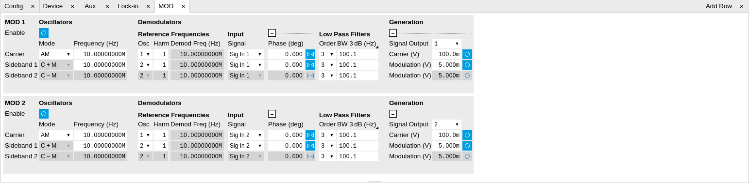
The modulation units are designed for experiments involving multiple frequencies. For many of such experiments the associated spectrum reveals a dominant center frequency, often called the carrier, and one or multiple sidebands symmetrically placed around the carrier. Typical examples are amplitude modulated (AM) signals with one carrier and two sidebands separated from the carrier by the AM modulation frequency. Another example is frequency modulation (FM) where multiple sidebands to the left and right of the carrier can appear. The relative amplitude of the sideband for both AM and FM depends on the modulation depth, which is often expressed by the modulation index.
The classical approach of analyzing such signals (in particular when only analog instruments are available) is to use a configuration called tandem demodulation. This is essentially the serial cascading of lock-in amplifiers. The first device is referenced to the carrier frequency and outputs the in-phase component. This is then fed into the subsequent lock-in amplifiers in order to extract the different sideband components. There are several downsides to this scheme:
- The quadrature component of the first lock-in tuned to the carrier has to be continuously zeroed out by adjusting the reference phase. Otherwise a serious part of the signal power is lost for the analysis which usually leads to a drop in SNR.
- The scheme scales badly in terms of the hardware resources needed, in particular if multiple sideband frequencies need to be extracted.
- Every time a signal enters or exits an instrument the SNR gets smaller (e.g. due to the instrument inputs noise). Multiple such steps can deteriorate signal quality significantly.
All these shortcomings are nicely overcome by providing the ability to generate linear combinations of oscillator frequencies and use these combinations as demodulation references.
The MOD tab contains two sections MOD 1 and MOD 2. Both are identical in all aspects except that MOD 1 is linked to demodulators 1, 2 and 3, whereas MOD 2 is linked to demodulators 5, 6, and 7. Each of the MOD units can make use of up to 3 oscillators, which can be even referenced to an external source by using ExtRef or a PLL. Figure 2 gives an overview of the different components involved and their interconnections.

For convenience the UI provides access to presets for AM and FM in the Mode column. In Manual Mode all settings can be chosen freely. When there are more than three frequencies present on a single signal one can even associate both sections MOD 1 and 2 to the same Signal Input.
Note
Whenever a MOD unit is enabled, all the settings in the Lock-in tab that are controlled by this unit will be set to read-only.
On top of signal analysis the UHF-MOD AM/FM Modulation option can also be utilized for signal generation. The Generation section provides all the necessary controls to adjust the carrier and sideband amplitudes.
Note
FM signals are generated by coherent superposition of the carrier signal with two sideband frequencies on either side that have the same amplitudes but opposite phases. The phase shift is achieved by using negative amplitudes as displayed in the Lock-in tab. This FM generation method approximates true FM as long as the modulation index is well below 1, i.e. higher-order sidebands can be neglected. For a modulation index of 1 true FM provides more than 13% of signal power in the second and higher order sidebands.
More details regarding AM and FM signal analysis and generation can be found on the Zurich Instruments web page.
Functional Elements
| Control/Tool | Option/Range | Description |
|---|---|---|
| Enable | ON / OFF | Enable the modulation |
| Mode | AM/FM/manual | Select the modulation mode. |
| Mode | Enabling of the first sideband and selection of the position of the sideband relative to the carrier frequency for manual mode. | |
| Off | First sideband is disabled. The sideband demodulator behaves like a normal demodulator. | |
| C + M | First sideband to the right of the carrier | |
| C - M | First sideband to the left of the carrier | |
| Mode | Enabling of the second sideband and selection of the position of the sideband relative to the carrier frequency for manual mode. | |
| Off | Second sideband is disabled. The sideband demodulator behaves like a normal demodulator. | |
| C + M | Second sideband to the right of the carrier | |
| C - M | Second sideband to the left of the carrier | |
| Frequency (Hz) | 0 to 600 MHz | Sets the frequency of the carrier. |
| Frequency (Hz) | 0 to 600 MHz | Frequency offset to the carrier from the first sideband. |
| Frequency (Hz) | 0 to 600 MHz | Frequency offset to the carrier from the second sideband. |
| Carrier | oscillator index | Select the oscillator for the carrier signal. |
| Sideband 1 | oscillator index | Select the oscillator for the first sideband. |
| Sideband 2 | oscillator index | Select the oscillator for the second sideband. |
| Harm | 1 to 1023 | Set harmonic of the carrier frequency. 1=Fundamental |
| Harm | 1 to 1023 | Set harmonic of the first sideband frequency. 1 = fundamental |
| Harm | 1 to 1023 | Set harmonic of the second sideband frequency. 1 = fundamental |
| Demod Freq (Hz) | 0 to 600 MHz | Carrier frequency used for the demodulation and signal generation on the carrier demodulator. |
| Demod Freq (Hz) | 0 to 600 MHz | Absolute frequency used for demodulation and signal generation on the first sideband demodulator. |
| Demod Freq (Hz) | 0 to 600 MHz | Absolute frequency used for demodulation and signal generation on the second sideband demodulator. |
| Channel | Signal Inputs, Trigger Inputs, Auxiliary Inputs, Auxiliary Outputs, Phase Demod 4, Phase Demod 8 | Select Signal Input for the carrier demodulation |
| Channel | Signal Inputs, Trigger Inputs, Auxiliary Inputs, Auxiliary Outputs, Phase Demod 4, Phase Demod 8 | Select Signal Input for the sideband demodulation |
| Phase | -180° to 180° | Phase shift applied to the reference input of the carrier demodulator and also to the carrier signal on the Signal Outputs |
| Phase | -180° to 180° | Phase shift applied to the reference input of the sideband demodulator and also to the sideband signal on the Signal Outputs |
| Zero |  |
Adjust the carrier demodulator's reference phase automatically in order to read zero degrees at the demodulator output. This action maximizes the X output, zeros the Y output, zeros the Θ output, and leaves the R output unchanged. |
| Zero | |
Adjust the sideband demodulator's reference phase automatically in order to read zero degrees at the demodulator output. This action maximizes the X output, zeros the Y output, zeros the Θ output, and leaves the R output unchanged. |
| Order | 1 to 8 | Filter order used for carrier demodulation |
| Order | 1 to 8 | Filter order used for sideband demodulation |
| TC/BW Value | numeric value | Defines the low-pass filter characteristic in the unit defined above for the carrier demodulation |
| TC/BW Value | numeric value | Defines the low-pass filter characteristic in the unit defined above for the sideband demodulation |
| Signal Output | 1, 2 or both | Select Signal Output 1, 2 or none |
| Carrier (V) | -range to range | Set the carrier amplitude |
| Modulation (V) | -range to range | Set the amplitude of the first sideband component. |
| Modulation (V) | -range to range | Set the amplitude of the second sideband component. |
| Index | -range to range | In FM mode, set modulation index value. The modulation index equals peak deviation divided by modulation frequency. |
| Peak Dev (Hz) | -range to range | In FM mode, set peak deviation value. |
| Enable FM Peak Mode | ON / OFF | In FM mode, choose to work with either modulation index or peak deviation. The modulation index equals peak deviation divided by modulation frequency. |
| Enable | ON / OFF | Enable the signal generation for the first sideband |
| Enable | ON / OFF | Enable the signal generation for the second sideband |
| Enable | ON / OFF | Enable the carrier signal |