DIO Tab
The DIO tab provides access to the settings and controls of the digital I/O as well as the Trigger channels and is available on all UHF Series instruments.
Features
- Monitor and control of digital I/O connectors
- Control settings for external reference and triggering
Description
The DIO tab is the main panel to control the digital inputs and outputs as well as the trigger levels and external reference channels . Whenever the tab is closed or an additional one of the same type is needed, clicking the following icon will open a new instance of the tab.
| Control/Tool | Option/Range | Description |
|---|---|---|
| DIO | Gives access to all controls relevant for the digital inputs and outputs including DIO, Trigger Inputs, Trigger Outputs, and Marker Outputs. |
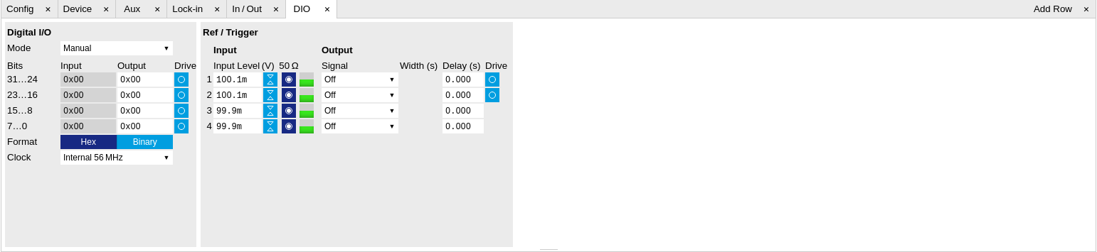
The Digital I/O section provides numerical monitors to observe the states of the digital inputs and outputs. Moreover, with the values set in the Output column and the Drive button activated the states can also be actively set in different numerical formats.
The Ref/Trigger section shows the settings for the 6 reference and trigger inputs and outputs. The two BNC connectors on the front panel are numbered 1 and 2 and can act as inputs as well as outputs. The first two lines in this section are associated to these front panel connectors. On the back panel of the Instrument are 2 more trigger inputs (line 3 and 4, left columns) and 2 more trigger outputs (line 3 and 4, right columns). All four are SMA connectors.
Note
The Input Level determines the trigger threshold for trigger state discrimination. Also a 100 mV hysteresis is applied that cannot be adjusted such that a minimum amplitude of more than 100 mV is needed for the Trigger inputs to work reliably.
Functional Elements
| Control/Tool | Option/Range | Description |
|---|---|---|
| DIO mode | Select DIO mode | |
| Manual | Enables manual control of the DIO output bits. | |
| AWG Sequencer | Enables setting of DIO output values by AWG sequencer commands. | |
| QA Results | Enables setting of DIO output values by QA results. | |
| QA Results QCCS | Enables setting of DIO output values by QA results compatible with the QCCS. | |
| QA Result Overflow | grey/yellow/red | Red: present overflow condition on the DIO interface during readout. Yellow: indicates an overflow occurred in the past. An overflow can happen if readouts are triggered faster than the maximum possible data-rate of the DIO interface. |
| DIO bits | label | Partitioning of the 32 bits of the DIO into 4 buses of 8 bits each. Each bus can be used as an input or output. |
| DIO input | numeric value in either Hex or Binary format | Current digital values at the DIO input port. |
| DIO output | numeric value in either hexadecimal or binary format | Digital output values. Enable drive to apply the signals to the output. |
| DIO drive | ON / OFF | When on, the corresponding 8-bit bus is in output mode. When off, it is in input mode. |
| Format | Select DIO view format. | |
| Hexadecimal | DIO view format is hexadecimal. | |
| Binary | DIO view format is binary. | |
| Clock | Select DIO internal or external clocking. | |
| Internal 56 MHz | The DIO is internally clocked with a frequency of 56.25 MHz. | |
| Clk Pin 68 | The DIO is externally clocked with a clock signal connected to DIO Pin 68. Available frequency range 1 Hz to 56.25 MHz. |
|
| Internal 50 MHz | The DIO is internally clocked with a frequency of 50 MHz. | |
| Trigger level | -5 V to 5 V | Trigger voltage level at which the trigger input toggles between low and high. Use 50% amplitude for digital input and consider the trigger hysteresis. |
| Auto Threshold | Press once | Automatically adjust the trigger threshold. The level is adjusted to fall in the center of the applied transitions. |
| 50 Ω | 50 Ω/1 kΩ | Trigger input impedance: When on, the trigger input impedance is 50 Ω, when off 1 kΩ. |
| Trigger Input Low status | Indicates the current low level trigger state. | |
| Off | A low state is not being triggered. | |
| On | A low state is being triggered. | |
| Trigger Input High status | Indicates the current high level trigger state. | |
| Off | A high state is not being triggered. | |
| On | A high state is being triggered. | |
| Trigger output signal | Select the signal assigned to the trigger output. | |
| Off | The output trigger is disabled. | |
| Osc Phase Demod 4/8 | Oscillator phase of demod 4 (trigger output channel 1) or demod 8 (trigger output channel 2).Trigger event is output for each zero crossing of the oscillator phase. | |
| Scope Trigger | Trigger output is asserted when the scope trigger condition is satisfied. | |
| Scope /Trigger | Trigger output is deasserted when the scope trigger condition is satisfied. | |
| Scope Armed | Trigger output is asserted when the scope is waiting for the trigger condition to become satisfied. | |
| Scope /Armed | Trigger output is deasserted when the scope is waiting for the trigger condition to become satisfied. | |
| Scope Active | Trigger output is asserted when the scope has triggered and is recording data. | |
| Scope /Active | Trigger output is deasserted when the scope has triggered and is recording data. | |
| AWG Marker 1 | Trigger output is assigned to one of the AWG Marker channels attached to AWG waveform data. | |
| AWG Marker 2 | Trigger output is assigned to one of the AWG Marker channels attached to AWG waveform data. | |
| AWG Marker 3 | Trigger output is assigned to one of the AWG Marker channels attached to AWG waveform data. | |
| AWG Marker 4 | Trigger output is assigned to one of the AWG Marker channels attached to AWG waveform data. | |
| AWG Active | Trigger output is asserted when the AWG is enabled. | |
| AWG Waiting | Trigger output is asserted when the AWG is waiting for external triggers, for a clock timer, or for other events. | |
| AWG Fetching | Trigger output is asserted when the AWG is fetching data from the main waveform and instruction memory. | |
| AWG Playing | Trigger output is asserted when the AWG is playing waveforms. | |
| AWG Trigger 1 | Trigger output is assigned to one of the AWG Trigger channels controlled by AWG sequencer commands. | |
| AWG Trigger 2 | Trigger output is assigned to one of the AWG Trigger channels controlled by AWG sequencer commands. | |
| AWG Trigger 3 | Trigger output is assigned to one of the AWG Trigger channels controlled by AWG sequencer commands. | |
| AWG Trigger 4 | Trigger output is assigned to one of the AWG Trigger channels controlled by AWG sequencer commands. | |
| MDS Clock Out | Trigger output is driven by the multi-device synchronisation clock. | |
| MDS Sync Out | Trigger output is driven by the multi-device synchronisation signal. | |
| Delay (s) | This delay adds an offset that acts only on the trigger/marker output. The total delay to the trigger/marker output is the sum of this value and the value of the output delay node. | |
| Width | 0 s to 0.149 s | Defines the minimal pulse width for the case of Scope and AWG Trigger/Active events written to the trigger outputs of the device. |
| Delay | 0 ns to 2.4 ns | Controls the delay of the Ref / Trigger output. The resolution is 78 ps. |
| Trigger drive | ON / OFF | When on, the bidirectional trigger on the front panel is in output mode. When off, the trigger is in input mode. |