AWG Tab
The AWG tab is available on UHFAWG Arbitrary Waveform Generator instruments and on UHFLI Lock-in Amplifier instruments with installed UHF-AWG Arbitrary Waveform Generator option (see Information section in the Device tab).
Features
- Dual-channel arbitrary waveform generator
- 128 MSa waveform memory per channel
- Sequence branching
- Digital modulation
- Multi-instrument synchronization
- Sequence program distribution over multiple instruments
- Cross-domain trigger engine
- Sequence Editor with code highlighting and auto completion
- High-level programming language with waveform generation and editing toolset
- Waveform viewer
Description
The AWG tab gives access to the arbitrary waveform generator functionality. Whenever the tab is closed or an additional one of the same type is needed, clicking the following icon will open a new instance of the tab.
| Control/Tool | Option/Range | Description |
|---|---|---|
| AWG | Generate arbitrary signals using sequencing and sample-by-sample definition of waveforms. |
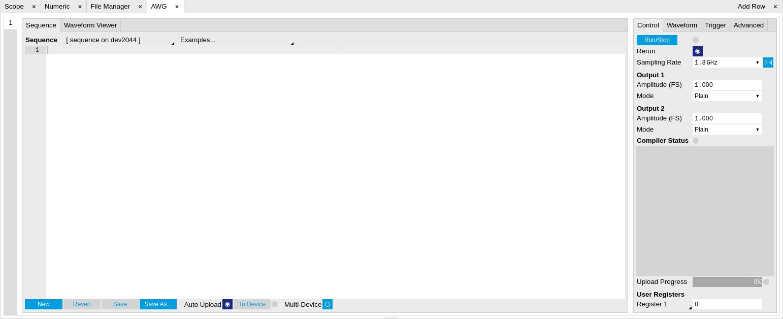
The AWG tab (see Figure 1) consists of a settings section on the right side and the Sequence and Waveform Viewer sub-tabs on the left side. The settings section is further divided into Control, Waveform, Trigger, and Advanced sub-tabs. The Sequence sub-tab is used for displaying, editing and compiling a LabOne sequence program. The sequence program defines which waveforms are played and in which order. The Sequence Editor is the main tool for operating the AWG.
A number of sequence programming examples are available through a drop-down menu at the top of the Sequence Editor, and additional ones can be found in Arbitrary Waveform Generator . The LabOne sequence programming language is specified in detail in LabOne Sequence Programming. The language comes with a number of predefined waveforms, such as Gaussian, Blackman, sine, or square functions. By combining those predefined waveforms using the waveform editing tools (add, multiply, cut, concatenate, etc), signals with a high level of complexity can be generated directly from the Sequence Editor window. Sample-by-sample definition of the output signal is possible by using comma-separated value (CSV) files specified by the user , see Waveform Generation and Playbackfor an example.
The AWG features a compiler which translates the high-level sequence program into machine instructions and waveform data to be stored in the instrument memory as shown in Figure 2. The sequence program is written using high-level control structures and syntax that are inspired by human language, whereas machine instructions reflect exactly what happens on the hardware level. Writing the sequence program using a high-level language represents a more natural and efficient way of working in comparison to writing lists of machine instructions, which is the traditional way of programming AWGs. Concretely, the improvements rely on features such as:
- combination of waveform generation, editing, and playback sequence in a single script
- easily readable syntax and naming for run-time variables and constants
- optimized waveform memory management, reduced transfers upon waveform changes
- definition of user functions and procedures for advanced structuring
- syntax validation
By design, there is no one-to-one link between the list of statements in the high-level language and the list of instructions executed by the Sequencer. There are cases in which a more detailed understanding of the Sequencer instruction list, and in particular its execution timing, is needed. Typically this is the case when observing delays or other signal timing properties that are unexpected from looking at the high-level script. Often such problems can be solved with a few adjustments to the program. Please see Debugging Sequencer Programs for practical advice.

The Sequence Editor provides the editing, compilation, and transfer
functionality for sequence programs. A program typed into the Editor is
compiled upon clicking  .
If the compilation is successful and Automatic Upload is enabled, the
program including all necessary waveform data is transferred to the
device. If the compilation fails, the Status field will display debug
messages. Clicking on
.
If the compilation is successful and Automatic Upload is enabled, the
program including all necessary waveform data is transferred to the
device. If the compilation fails, the Status field will display debug
messages. Clicking on  allows you to choose a new name for the program. The name of the program
that is currently edited is displayed at the top of the editor. External
program files as well as waveform data files can be transferred to the
right location easily using the file drag-and-drop zone in the
Config Tab
so they become accessible from the user interface. The files can be
managed in the
File Manager Tab
and their location in the directory structure is shown in
Table 2. The program
name is displayed in a drop-down box. The box allows quick access to all
programs in the standard sequence program location. It is possible to
quickly switch between programs using the box. Changes made in one
program will be preserved when switching to a different program. The
file name of a program will be postfixed by an asterisk in case there
are unsaved changes in the source file. Note that switching programs in
the editor is not sufficient to also update the program in the
instrument. In order to send a newly selected program to the instrument,
the
allows you to choose a new name for the program. The name of the program
that is currently edited is displayed at the top of the editor. External
program files as well as waveform data files can be transferred to the
right location easily using the file drag-and-drop zone in the
Config Tab
so they become accessible from the user interface. The files can be
managed in the
File Manager Tab
and their location in the directory structure is shown in
Table 2. The program
name is displayed in a drop-down box. The box allows quick access to all
programs in the standard sequence program location. It is possible to
quickly switch between programs using the box. Changes made in one
program will be preserved when switching to a different program. The
file name of a program will be postfixed by an asterisk in case there
are unsaved changes in the source file. Note that switching programs in
the editor is not sufficient to also update the program in the
instrument. In order to send a newly selected program to the instrument,
the  button must be clicked.
| File type | Location |
|---|---|
| Waveform files (Windows) | C:\Users\<user name>\Documents\Zurich Instruments\LabOne\WebServer\awg\waves |
| Sequence programs (Windows) | C:\Users\<user name>\Documents\Zurich Instruments\LabOne\WebServer\awg\src |
| Waveform files (Linux) | ~/Zurich Instruments/LabOne/WebServer/awg/waves |
| Sequence programs (Linux) | ~/Zurich Instruments/LabOne/WebServer/awg/src |
In the Control sub-tab the user configures signal parameters and
controls the execution of the AWG. The AWG can be started in by clicking
on  .
When enabling the Rerun button, the Sequencer will be restarted
automatically when its program completes. The continuous mode is a
simple way to create an infinite loop, but it results in a considerable
timing jitter. To avoid this jitter, it is recommended to specify
infinite loops directly in the sequence program.
.
When enabling the Rerun button, the Sequencer will be restarted
automatically when its program completes. The continuous mode is a
simple way to create an infinite loop, but it results in a considerable
timing jitter. To avoid this jitter, it is recommended to specify
infinite loops directly in the sequence program.
The Sampling Rate field is used to control the default playback sampling rate of the AWG. The sampling rate is dynamic, i.e., can be specified for each waveform by using an optional argument in the waveform playback instructions in the sequence program. This allows for considerably reducing waveform upload time for signals that contain both fast and slow components. The two Output sections are used to configure the AWG output mode and signal amplitude. The AWG output channels are not the same as the physical Signal Outputs of the instrument. The AWG output channels are routed to the Signal Outputs of the device. The Amplitude value is a gain parameter, 1.0 by default, that is applied to waveforms on the way from the AWG output channel to the Signal Output. The Amplitude value gives a means to rescale the signal independently of the programmed waveforms. The Mode control is used to enable or disable the modulation mode , or to enable advanced modulation mode . With enabled modulation, the signal of an AWG Output is multiplied with an oscillator signal prior to being sent to the Signal Output. This is useful for the case where the desired signal can be described as a sinusoidal carrier with a shaped envelope. The advanced modulation mode allows you to modulate multiple carriers (up to 4) with individual envelope waveforms. Please read more about use cases, advantages, and practical examples in Modulation Mode.
The generation of the modulated signal depends on the settings made in
the Lock-in tab. Figure 3 shows how the signals are
routed internally on their way from the oscillators and the AWG to the
Signal Outputs. There are two switches in the diagram. The upper switch
is related to the AWG Mode selection. In Modulation mode, the signal
coming from the AWG unit 1 (2) is multiplied with the oscillator signal
of demodulator 4 (8). The phase and harmonic of the oscillator signal
can be adjusted in the Lock-in tab. In Direct mode, the AWG signal is
multiplied with a constant 1.0, in other words, it remains unchanged.
The lower switch is related to the running state of the AWG, i.e, the
 buttons. When the AWG is idle, the Output Amplitude setting from the
Lock-in tab takes the place of the AWG signal. This is the standard
configuration for lock-in measurements. It is furthermore useful for
defining the voltage appearing on the Signal Output when the AWG is off.
The UHF-MF Multi-frequency option provides additional oscillators as
well as an Oscillator Select switch matrix at the input of the
demodulators, enabling the use of up to 8 independent frequencies for
modulation. The Register values may be used as integer variables inside
a sequence program, for instance to vary a delay between pulses manually
or with the
Sweeper Tab.
buttons. When the AWG is idle, the Output Amplitude setting from the
Lock-in tab takes the place of the AWG signal. This is the standard
configuration for lock-in measurements. It is furthermore useful for
defining the voltage appearing on the Signal Output when the AWG is off.
The UHF-MF Multi-frequency option provides additional oscillators as
well as an Oscillator Select switch matrix at the input of the
demodulators, enabling the use of up to 8 independent frequencies for
modulation. The Register values may be used as integer variables inside
a sequence program, for instance to vary a delay between pulses manually
or with the
Sweeper Tab.

The Waveform sub-tab displays information about the waveforms that are used by the current sequence program, such as their length and channel number. Together with the Waveform viewer sub-tab, it is a useful tool to visualize the waveforms used in the sequence program.
On the Trigger sub-tab you can configure the trigger inputs of the AWG and control the Cross-Domain Trigger functionality of the instrument. The AWG has four trigger input channels which can be configured to probe a variety of signals coming both from internal (e.g. demodulator output data) or external (e.g. Ref/Trigger input) sources . This means that the AWG trigger input channels are not the same as physical device inputs. Two of the trigger input channels are called analog (meaning they can accept signals of continuous, analog-like character), and two are called digital (meaning they can accept binary signals). Trigger Level and Hysteresis may be configured for the Analog Triggers, and the user can select between rising and falling edge trigger functionality. The primary use of the triggers is to control the timing of the AWG signal relative to an external device. Another use of triggers is to implement sequence branching. See Triggering and Synchronization and Branching and Feed-Forward for practical examples on how to use the AWG trigger in- and outputs.
The Advanced sub-tab displays the compiled list of sequencer instructions and the current state of the sequencer on the instrument. This can help an advanced user in debugging a sequence program and understanding its execution.
Sequence Editor Keyboard Shortcuts
The tables below list a number of helpful keyboard shortcuts that are applicable in the LabOne Sequence Editor.
| Shortcut | Action |
|---|---|
| Ctrl+D | Remove line |
| Alt+Shift+Down | Copy lines down |
| Alt+Shift+Up | Copy lines up |
| Alt+Down | Move lines down |
| Alt+Up | Move lines up |
| Alt+Del | Remove to line end |
| Alt+Backspace | Remove to line start |
| Ctrl+Backspace | Remove word left |
| Ctrl+Del | Remove word right |
| Shortcut | Action |
|---|---|
| Ctrl+A | Select all |
| Shift+Left | Select left |
| Shift+Right | Select right |
| Ctrl+Shift+Left | Select word left |
| Ctrl+Shift+Right | Select word right |
| Shift+Home | Select line start |
| Shift+End | Select line end |
| Alt+Shift+Right | Select to line end |
| Alt+Shift+Left | Select to line start |
| Shift+Up | Select up |
| Shift+Down | Select down |
| Shift+Page Up | Select page up |
| Shift+Page Down | Select page down |
| Ctrl+Shift+Home | Select to start |
| Ctrl+Shift+End | Select to end |
| Ctrl+Shift+D | Duplicate selection |
| Ctrl+Shift+P | Select to matching bracket |
| Shortcut | Action |
|---|---|
| Left | Go to left |
| Right | Go to right |
| Ctrl+Left | Go to word left |
| Ctrl+Right | Go to word right |
| Up | Go line up |
| Down | Go line down |
| Alt+Left, Home | Go to line start |
| Alt+Right, End | Go to line end |
| Page Up | Go to page up |
| Page Down | Go to page down |
| Ctrl+Home | Go to start |
| Ctrl+End | Go to end |
| Ctrl+L | Go to line |
| Ctrl+Down | Scroll line down |
| Ctrl+Up | Scroll line up |
| Ctrl+P | Go to matching bracket |
| Shortcut | Action |
|---|---|
| Ctrl+F | Find |
| Ctrl+H | Replace |
| Ctrl+K | Find next |
| Ctrl+Shift+K | Find previous |
| Shortcut | Action |
|---|---|
| Alt+L | Fold selection |
| Alt+Shift+L | Unfold |
| Shortcut | Action |
|---|---|
| Tab | Indent |
| Shift+Tab | Outdent |
| Ctrl+Z | Undo |
| Ctrl+Shift+Z, Ctrl+Y | Redo |
| Ctrl+/ | Toggle comment |
| Ctrl+Shift+U | Change to lower case |
| Ctrl+U | Change to upper case |
| Ins | Overwrite |
| Ctrl+Shift+E | Macros replay |
| Ctrl+Alt+E | Macros recording |
| Del | Delete |
LabOne Sequence Programming
A Simple Example
The syntax of the LabOne AWG Sequencer programming language is based on C, but with a few simplifications. Each statement is concluded with a semicolon, several statements can be grouped with curly brackets, and comment lines are identified with a double slash. The following example shows some of the fundamental functionalities: waveform generation, repeated playback, triggering, and single/dual-channel waveform playback. See Arbitrary Waveform Generator for a step-by-step introduction with more examples.
// Define an integer constant
const N = 4096;
// Create two Gaussian pulses with length N points,
// amplitude +1.0 (-1.0), center at N/2, and a width of N/8
wave gauss_pos = 1.0*gauss(N, N/2, N/8);
wave gauss_neg = -1.0*gauss(N, N/2, N/8);
// execute playback sequence 100 times
repeat (100) {
  // Play pulse on AWG channel 1
  playWave(gauss_pos);
  // Play pulses simultaneously on both AWG channels
  playWave(gauss_pos, gauss_neg);
  // Wait 8000 samples
  playZero(8000);
}
Keywords and Comments
The following table lists the keywords used in the LabOne AWG Sequencer language.
| Keyword | Description |
|---|---|
const |
Constant declaration |
var |
Integer variable declaration |
cvar |
Compile-time variable declaration |
string |
Constant string declaration |
true |
Boolean true constant |
false |
Boolean false constant |
for |
For-loop declaration |
while |
While-loop declaration |
repeat |
Repeat-loop declaration |
if |
If-statement |
else |
Else-part of an if-statement |
switch |
Switch-statement |
case |
Case-statement within a switch |
default |
Default-statement within a switch |
return |
Return from function or procedure, optionally with a return value |
The following code example shows how to use comments.
const a = 10; // This is a line comment. Everything between the double
              // slash and the end of the line will be ignored.

/* This is a block comment. Everything between the start-of-block-comment
and end-of-block-comment markers is ignored.

For example, the following statement will be ignored by the compiler.
const b = 100;
*/
Constants and Variables
Constants may be used to make the program more readable. They may be
of integer or floating-point type. It must be possible for the compiler
to compute the value of a constant at compile time, i.e., on the host
computer. Constants are declared using the const keyword.
Compile-time variables may be used in computations and loop
iterations during compile time, e.g. to create large numbers of
waveforms in a loop. They may be of integer or floating-point type. They
are used in a similar way as constants, except that they can change
their value during compile time operations. Compile-time variables are
declared using the cvar keyword.
Variables may be used for making simple computations during run
time, i.e., on the instrument. The Sequencer supports integer variables,
addition, and subtraction. Not supported are floating-point variables,
multiplication, and division. Typical uses of variables are to step
waiting times , to output DIO values, or to tag digital measurement data
with a numerical identifier. Variables are declared using the var
keyword.
The following code example shows how to use variables.
var b = 100; // Create and initialize a variable

// Repeat the following block of statements 100 times
repeat (100) {
  b = b + 1; // Increment b
  wait(b);   // Wait 'b' cycles
}
The following table shows the predefined constants. These constants are intended to be used as arguments in certain run-time evaluated functions that encode device parameters with integer numbers. For example, the AWG Sampling Rate is specified as an integer exponent n in the expression (1.8 GSa/s)/2n.
| Name | Value | Description |
|---|---|---|
| AWG_RATE_1800MHZ | 0 | Constant to set Sampling Rate to 1.8 GHz. |
| AWG_RATE_900MHZ | 1 | Constant to set Sampling Rate to 900 MHz. |
| AWG_RATE_450MHZ | 2 | Constant to set Sampling Rate to 450 MHz. |
| AWG_RATE_225MHZ | 3 | Constant to set Sampling Rate to 225 MHz. |
| AWG_RATE_112MHZ | 4 | Constant to set Sampling Rate to 112 MHz. |
| AWG_RATE_56MHZ | 5 | Constant to set Sampling Rate to 56 MHz. |
| AWG_RATE_28MHZ | 6 | Constant to set Sampling Rate to 28 MHz. |
| AWG_RATE_14MHZ | 7 | Constant to set Sampling Rate to 14 MHz. |
| AWG_RATE_7MHZ | 8 | Constant to set Sampling Rate to 7 MHz. |
| AWG_RATE_3P5MHZ | 9 | Constant to set Sampling Rate to 3.5 MHz. |
| AWG_RATE_1P8MHZ | 10 | Constant to set Sampling Rate to 1.8 MHz. |
| AWG_RATE_880KHZ | 11 | Constant to set Sampling Rate to 880 kHz. |
| AWG_RATE_440KHZ | 12 | Constant to set Sampling Rate to 440 kHz. |
| AWG_RATE_220KHZ | 13 | Constant to set Sampling Rate to 220 kHz. |
| AWG_MONITOR_TRIGGER | 0x0000020 | Constant to activate the trigger of the Monitor unit. |
| AWG_INTEGRATION_TRIGGER | 0x0000010 | Constant to activate the trigger of the Integration units. |
| AWG_INTEGRATION_ARM | 0x3ff0000 | Constant to arm the Integration units. |
| DEVICE_SAMPLE_RATE | <actual device sample rate> | |
| AWG_CHAN1 | 1 | Constant to select channel 1. |
| AWG_CHAN2 | 2 | Constant to select channel 2. |
| AWG_MARKER1 | 1 | Constant to select marker 1. |
| AWG_MARKER2 | 2 | Constant to select marker 2. |
| AWG_OSC_PHASE_START | 1 | Constant to trigger the oscillator phase on the positive edge. |
| AWG_OSC_PHASE_MIDDLE | 0 | Constant to trigger the oscillator phase on the negative edge. |
Numbers can be expressed using either of the following formatting.
const a = 10;            // Integer notation
const b = -10;           // Negative number
const h = 0xdeadbeef;    // Hexadecimal integer
const bin = 0b10101;     // Binary integer
const f = 0.1e-3;        // Floating point number.
const not_float = 10e3;  // Not a floating point number
Booleans are specified with the keywords true and false.
Furthermore, all numbers that evaluate to a nonzero value are considered
true. All numbers that evaluate to zero are considered false.
Strings are delimited using "" and are interpreted as constants. Strings may be concatenated using the + operator.
string AWG_PATH = "awgs/0/";
string AWG_GAIN_PATH = AWG_PATH + "gains/0";
Waveform Generation and Editing
The following table contains the definition of functions for waveform generation.
wave zeros(const samples) 
Constant amplitude of 0 over the defined number of samples.
Args:
samples:Number of samples in the waveform
Returns:
resulting waveform
wave ones(const samples) 
Constant amplitude of 1 over the defined number of samples.
Args:
samples:Number of samples in the waveform
Returns:
resulting waveform
wave sine(const samples, const amplitude=1.0, const phaseOffset, const nrOfPeriods) 
Sine function with arbitrary amplitude (a), phase offset in radians (p), number of periods (f) and number of samples (N).
Args:
-
amplitude:Amplitude of the signal (optional) -
nrOfPeriods:Number of Periods within the defined number of samples -
phaseOffset:Phase offset of the signal in radians -
samples:Number of samples in the waveform
Returns:
resulting waveform
wave cosine(const samples, const amplitude=1.0, const phaseOffset, const nrOfPeriods) 
Cosine function with arbitrary amplitude (a), phase offset in radians (p), number of periods (f) and number of samples (N).
Args:
-
amplitude:Amplitude of the signal (optional) -
nrOfPeriods:Number of Periods within the defined number of samples -
phaseOffset:Phase offset of the signal in radians -
samples:Number of samples in the waveform
Returns:
resulting waveform
wave sinc(const samples, const amplitude=1.0, const position, const beta) 
Normalized sinc function with control of peak position (p), amplitude (a), width (\beta) and number of samples (N).
Args:
-
amplitude:Amplitude of the signal (optional) -
beta:Width of the function -
position:Peak position of the function -
samples:Number of samples in the waveform
Returns:
resulting waveform
wave ramp(const samples, const startLevel, const endLevel) 
Linear ramp from the start (s) to the end level (e) over the number of samples (N).
Args:
-
endLevel:level at the last sample of the waveform -
samples:Number of samples in the waveform -
startLevel:level at the first sample of the waveform
Returns:
resulting waveform
wave sawtooth(const samples, const amplitude=1.0, const phaseOffset, const nrOfPeriods) 
Sawtooth function with arbitrary amplitude, phase in radians and number of periods.
Args:
-
amplitude:Amplitude of the signal -
nrOfPeriods:Number of Periods within the defined number of samples -
phaseOffset:Phase offset of the signal in radians -
samples:Number of samples in the waveform
Returns:
resulting waveform
wave triangle(const samples, const amplitude=1.0, const phaseOffset, const nrOfPeriods) 
Triangle function with arbitrary amplitude, phase in radians and number of periods.
Args:
-
amplitude:Amplitude of the signal -
nrOfPeriods:Number of Periods within the defined number of samples -
phaseOffset:Phase offset of the signal in radians -
samples:Number of samples in the waveform
Returns:
resulting waveform
wave gauss(const samples, const amplitude=1.0, const position, const width) 
Gaussian pulse with arbitrary amplitude (a), position (p), width (w) and number of samples (N).
Args:
-
amplitude:Amplitude of the signal (optional) -
position:Peak position of the pulse -
samples:Number of samples in the waveform -
width:Width of the pulse
Returns:
resulting waveform
wave drag(const samples, const amplitude=1.0, const position, const width) 
Derivative of Gaussian pulse with arbitrary amplitude (a), position (p), width (w) and number of samples (N) normalized to a maximum amplitude of 1.
Args:
-
amplitude:Amplitude of the signal (optional) -
position:Center point position of the pulse -
samples:Number of samples in the waveform -
width:Width of the pulse
Returns:
resulting waveform
wave blackman(const samples, const amplitude=1.0, const alpha) 
Blackman window function with arbitrary amplitude (a), alpha parameter and number of samples (N).
Args:
-
alpha:Width of the function -
amplitude:Amplitude of the signal (optional) -
samples:Number of samples in the waveform
Returns:
resulting waveform
wave hamming(const samples, const amplitude=1.0) 
Hamming window function with arbitrary amplitude (a) and number of samples (N).
Args:
-
amplitude:Amplitude of the signal (optional) -
samples:Number of samples in the waveform
Returns:
resulting waveform
wave hann(const samples, const amplitude=1.0) 
Hann window function with arbitrary amplitude (a) and number of samples (N).
Args:
-
amplitude:Amplitude of the signal -
samples:Number of samples in the waveform
Returns:
resulting waveform
wave rect(const samples, const amplitude) 
Rectangle function, constants amplitude (a) over the defined number of samples.
Args:
-
amplitude:Amplitude of the signal -
samples:Number of samples in the waveform
Returns:
resulting waveform
wave marker(const samples, const markerValue) 
Generate a waveform with marker bits set to the specified value. The analog part of the waveform is zero.
Args:
-
markerValue:Value of the marker bits -
samples:Number of samples in the waveform
Returns:
resulting waveform
wave rand(const samples, const amplitude=1.0, const mean, const stdDev) 
White noise with arbitrary amplitude, power and standard deviation.
Args:
-
amplitude:Amplitude of the signal -
mean:Average signal level -
samples:Number of samples in the waveform -
stdDev:Standard deviation of the noise signal
Returns:
resulting waveform
wave randomGauss(const samples, const amplitude=1.0, const mean, const stdDev) 
White noise with arbitrary amplitude, power and standard deviation.
Args:
-
amplitude:Amplitude of the signal -
mean:Average signal level -
samples:Number of samples in the waveform -
stdDev:Standard deviation of the noise signal
Returns:
resulting waveform
wave randomUniform(const samples, const amplitude=1.0) 
Random waveform with uniform distribution.
Args:
-
amplitude:Amplitude of the signal -
samples:Number of samples in the waveform
Returns:
resulting waveform
wave lfsrGaloisMarker(const samples, const markerBit, const polynomial, const initial) 
Generate a waveform with specified marker bit set to the Galois LFSR (linear-feedback shift register) generated sequence. The analog part of the waveform is zero. The LFSR characteristic polynomial is a member of the Galois Field of two elements and represented in binary form. See wikipedia entries for "Finite field arithmetic" and "Linear-feedback shift register (Galois LFSR)".
Args:
-
initial:LFSR initial state, any nonzero value will work, usually 0x1 -
markerBit:Marker bit to set (1 or 2) -
polynomial:LFSR characteristic polynomial in binary representation (max shift length 32), use 0x90000 for QRSS / PRBS-20 -
samples:Number of samples in the waveform
Returns:
resulting waveform
wave chirp(const samples, const amplitude=1.0, const startFreq, const stopFreq, const phase=0) 
Frequency chirp function with arbitrary amplitude, start and stop frequency, initial phase in radians and number of samples. Start and stop frequency are expressed in units of the AWG Sampling Rate. The amplitude can only be defined if the initial phase is defined as well.
Args:
-
amplitude:Amplitude of the signal (optional) -
phase:Initial phase of the signal (optional) -
samples:Number of samples in the waveform -
startFreq:Start frequency of the signal -
stopFreq:Stop Frequency of the signal
Returns:
resulting waveform
wave rrc(const samples, const amplitude=1.0, const position, const beta, const width) 
Root raised cosine function with arbitrary amplitude (a), position (p), roll-off factor (\beta) and width (w) and number of samples (N).
Args:
-
amplitude:Amplitude of the signal -
beta:Roll-off factor -
position:Center point position of the pulse -
samples:Number of samples in the waveform -
width:Width of the pulse
Returns:
Resulting waveform
wave vect(const value,...) 
Specify a waveform sample by sample. Each sample is defined by one of an arbitrary number of input arguments. Only recommended for short waveforms that consist of less than 100 samples. Larger waveforms may be defined in a CSV file.
Args:
value:Waveform amplitude at the respective sample
Returns:
resulting waveform
wave placeholder(const samples, const marker0=false, const marker1=false) 
Creates space for a single-channel waveform, optionally with markers, without actually generating any waveform data when compiling the sequence program. Actual waveform data needs to be uploaded separately via the "<dev>/AWGS/<n>/WAVEFORM/WAVES/<index>" API nodes after the sequence compilation and upload. The waveform index can be explicitly assigned to the generated placeholder wave using the assignWaveIndex instruction.
Args:
-
marker0:true if marker bit 0 must be used (default false) -
marker1:true if marker bit 1 must be used (default false) -
samples:Number of samples in the waveform
Returns:
waveform object
The following table contains the definition of functions for waveform editing.
wave join(wave wave1, wave wave2, const interpolLength=0) 
Connect two or more waveforms with optional linear interpolation between the waveforms.
Args:
-
interpolLength:Number of samples to interpolate between waveforms (optional, default 0) -
wave1:Input waveform -
wave2:Input waveform
Returns:
joined waveform
wave join(wave wave1, wave wave2,...) 
Connect two or more waveforms.
Args:
-
wave1:Input waveform -
wave2:Input waveform
Returns:
joined waveform
wave interleave(wave wave1, wave wave2,...) 
Interleave two or more waveforms sample by sample.
Args:
-
wave1:Input waveform -
wave2:Input waveform
Returns:
interleaved waveform
wave add(wave wave1, wave wave2,...) 
Add two or more waveforms sample by sample. Alternatively, the "+" operator may be used for waveform addition.
Args:
-
wave1:Input waveform -
wave2:Input waveform
Returns:
sum waveform
wave multiply(wave wave1, wave wave2,...) 
Multiply two or more waveforms sample by sample. Alternatively, the "*" operator may be used for waveform multiplication.
Args:
-
wave1:Input waveform -
wave2:Input waveform
Returns:
product waveform
wave scale(wave waveform, const factor) 
Scale the input waveform with the factor and return the scaled waveform. The input waveform remains unchanged.
Args:
-
factor:Scaling factor -
waveform:Input waveform
Returns:
scaled waveform
wave flip(wave waveform) 
Flip the input waveform back to front and return the flipped waveform. The input waveform remains unchanged.
Args:
waveform:Input waveform
Returns:
flipped waveform
wave cut(wave waveform, const from, const to) 
Cuts a segment out of the input waveform and returns it. The input waveform remains unchanged. The segment is flipped in case that "from" is larger than "to".
Args:
-
from:First sample of the cut waveform -
to:Last sample of the cut waveform -
waveform:Input waveform
Returns:
cut waveform
wave filter(wave b, wave a, wave x) 
Filter generates a rational transfer function with the waveforms a and b as numerator and denominator coefficients. The transfer function is normalized by the first element of a, which has to be non-zero. The filter is applied to the input waveform x and returns the filtered waveform.
Args:
-
a:Denominator coefficients -
b:Numerator coefficients -
x:Input waveform
Returns:
filtered waveform
wave circshift(wave a, const n) 
Circularly shifts a 1D waveform and returns it.
Args:
-
n:Number of elements to shift -
waveform:Input waveform
Returns:
circularly shifted waveform
Waveform Playback and Predefined Functions
The following table contains the definition of functions for waveform playback and other purposes.
void setDIO(var value) 
Writes the value as a 32-bit value to the DIO bus.
The value can be either a const or a var value. Configure the Mode setting in the DIO tab when using this command. The DIO interface speed of 50 MHz limits the rate at which the DIO output value is updated.
Args:
value:The value to write to the DIO (const or var)
var getDIOTriggered() 
Reads a 32-bit value from the DIO bus as recorded at the last DIO trigger position.
Returns:
var containing the read value
void setTrigger(var value) 
Sets the AWG Trigger output signals.
The state of all four AWG Trigger output signals is represented by the bits in the binary representation of the integer value. Binary notation of the form 0b0000 is recommended for readability.
Args:
value:to be written to the trigger output lines
void wait(var cycles) 
Waits for the given number of Sequencer clock cycles (4.44 ns per cycle).
Args:
cycles:number of cycles to wait
void waitDIOTrigger() 
Waits until the DIO interface trigger is active. The trigger is specified by the Strobe Index and Strobe Slope settings in the AWG Sequencer tab.
var getDigTrigger(const index) 
Gets the state of the indexed Digital Trigger input (1 or 2 on UHF, 1-8 on HDAWG).
The physical signal connected to the AWG Digital Trigger input is to be configured in the Trigger sub-tab of the AWG tab.
Args:
index:index of the Digital Trigger input to be read; can be either 1 or 2 on UHF, or 1-8 on HDAWG
Returns:
trigger state, either 0 or 1
void error(string msg,...) 
Throws the given error message when reached.
Args:
msg:Message to be displayed
void info(string msg,...) 
Returns the specified message when reached.
Args:
msg:Message to be displayed
void setInt(string path, var value) 
Writes an integer value to one of the nodes in the device.
If the path does not start with a device identifier, then the current device is assumed.
Args:
-
path:The node path to be written to -
value:The integer value to be written
void setDouble(string path, var value) 
Writes a floating point value to one of the nodes in the device.
If the path does not start with a device identifier, then the current device is assumed.
Args:
-
path:The node path to be written to -
value:The integer or floating point value to be written
void setDouble(string path, var value, const scale) 
Writes a floating point value to one of the nodes in the device.
If the path does not start with a device identifier, then the current device is assumed.
Args:
-
path:The node path to be written to -
scale:Scaling value to be applied to the value before writing to the node -
value:The integer or floating point value to be written
void setID(var id) 
Sets the ID value that is attached to data streamed from the device to the host PC. The ID value is useful for synchronizing the data acquisition process in combination with the Sweeper or the Software Trigger. The ID value is denoted AWG Seq Index in the tree of tools like the plotter.
Args:
id:The new ID to be attached to streaming data of the device
void setSeqIndex(var id) 
Sets the ID value that is attached to data streamed from the device to the host PC. The ID value is useful for synchronizing the data acquisition process in combination with the Sweeper or the Software Trigger. The ID value is denoted AWG Seq Index in the tree of tools like the plotter. The setSeqIndex function is identical to the setID function.
Args:
id:The new ID to be attached to streaming data of the device
void sync() 
Perform Multi-Device synchronization command for all devices at this point. Leader/Follower assignment is automatic.
Only for programs running on multiply synchronized instruments.
void waitWave() 
Waits until the AWG is done playing the current waveform.
void randomSeed() 
Generate a new seed for the subsequent random vector commands.
void assignWaveIndex(const output, wave waveform, const index) 
void assignWaveIndex(wave waveform, const index) 
void playWave(const output, wave waveform, const rate=AWG_RATE_DEFAULT) 
Starts to play the given waveforms on the defined output channels. The playback begins as soon as the previous waveform playback is finished.
Args:
-
output:defines on which output the following waveform is played -
rate:sample rate with which the AWG plays the waveforms (default set in the user interface). -
waveform:waveform to be played
void playWave(const output, wave waveform,...) 
Starts to play the given waveforms on the defined output channels. It can contain multiple waveforms with an output definition. The playback begins as soon as the previous waveform playback is finished.
Args:
-
output:defines on which output the following waveform is played -
waveform:waveform to be played
void playWave(wave waveform, const rate=AWG_RATE_DEFAULT) 
Starts to play the given waveforms, output channels are assigned automatically depending on the number of input waveforms. The playback begins as soon as the previous waveform playback is finished.
Args:
-
rate:sample rate with which the AWG plays the waveforms (default set in the user interface). -
waveform:waveform to be played
void playWave(wave waveform,...) 
Starts to play the given waveforms, output channels are assigned automatically depending on the number of input waveforms. The playback begins as soon as the previous waveform playback is finished.
Args:
waveform:waveform to be played
void setUserReg(const register, var value) 
Writes a value to one of the User Registers (indexed 0 to 15).
The User Registers may be used for communicating information to the LabOne User Interface or a running API program.
Args:
-
register:The register index (0 to 15) to be written to -
value:The integer value to be written
var getUserReg(const register) 
Reads the value from one of the User Registers (indexed 0 to 15). The User Registers may be used for communicating information to the LabOne User Interface or a running API program.
Args:
register:The register to be read (0 to 15)
Returns:
current register value
void playZero(const samples) 
Starts to play zeros on all channels for the specified number of samples. Behaves as if same length all-zeros waveform is played using playWave, but without consuming waveform memory.
Args:
samples:Number of samples to be played. The same min length and granularity applies as for regular waveforms.
void playZero(const samples, const rate) 
Starts to play zeros on all channels for the specified number of samples. Behaves as if same length all-zeros waveform is played using playWave, but without consuming waveform memory.
Args:
-
rate:Sample rate with which the AWG plays zeros (default set in the user interface). -
samples:Number of samples to be played. The same min length and granularity applies as for regular waveforms.
void setRate(const rate) 
Overwrites the default Sampling Rate for the following playWave commands.
Args:
rate:New default sampling rate
void playWaveNow(const output, wave waveform, const rate=AWG_RATE_DEFAULT) 
Starts to play the given waveforms on the defined output channels. It starts immediately even if the previous waveform playback is still in progress.
Args:
-
output:defines on which output the following waveform is played -
rate:sample rate with which the AWG plays the waveforms (default set in the user interface). -
waveform:waveform to be played
void playWaveNow(const output, wave waveform,...) 
Starts to play the given waveforms on the defined output channels. It can contain multiple waveforms with an output definition. It starts immediately even if the previous waveform playback is still in progress.
Args:
-
output:defines on which output the following waveform is played -
waveform:waveform to be played
void playWaveNow(wave waveform, const rate=AWG_RATE_DEFAULT) 
Starts to play the given waveforms, channels are assigned automatically depending on the number of input waveforms. It starts immediately even if the previous waveform playback is still in progress.
Args:
-
rate:sample rate with which the AWG plays the waveforms (default set in the user interface). -
waveform:waveform to be played
void playWaveNow(wave waveform,...) 
Starts to play the given waveforms, channels are assigned automatically depending on the number of input waveforms. It starts immediately even if the previous waveform playback is still in progress.
Args:
waveform:waveform to be played
void playWaveIndexed(const output, wave waveform, var offset, const length, const rate=AWG_RATE_DEFAULT) 
Starts to play the specified part of the given waveforms on the defined output channels. It can contain multiple waveforms with an output definition. The playback begins as soon as the previous waveform playback is finished.
Args:
-
length:number of samples to be played from this waveform -
offset:offset in samples from the start of the waveform -
output:defines on which output the following waveform is played -
rate:sample rate with which the AWG plays the waveforms (default set in the user interface). -
waveform:waveform to be played
void playWaveIndexed(wave waveform, var offset, const length, const rate=AWG_RATE_DEFAULT) 
Starts to play the specified part of the given waveforms, channels are assigned automatically depending on the number of input waveforms. The playback begins as soon as the previous waveform playback is finished.
Args:
-
length:number of samples to be played from this waveform -
offset:offset in samples from the start of the waveform -
rate:sample rate with which the AWG plays the waveforms (default set in the user interface). -
waveform:waveform to be played
void playWaveIndexedNow(const output, wave waveform, var offset, const length, const rate=AWG_RATE_DEFAULT) 
Starts to play the specified part of the given waveforms on the defined output channels. It can contain multiple waveforms with an output definition. It starts immediately even if the previous waveform playback is still in progress.
Args:
-
length:number of samples to be played from this waveform -
offset:offset in samples from the start of the waveform -
output:defines on which output the following waveform is played -
rate:sample rate with which the AWG plays the waveforms (default set in the user interface). -
waveform:waveform to be played
void playWaveIndexedNow(wave waveform, var offset, const length, const rate=AWG_RATE_DEFAULT) 
Starts to play the specified part of the given waveforms, channels are assigned automatically depending on the number of input waveforms. It starts immediately even if the previous waveform playback is still in progress.
Args:
-
length:number of samples to be played from this waveform -
offset:offset in samples from the start of the waveform -
rate:sample rate with which the AWG plays the waveforms (default set in the user interface). -
waveform:waveform to be played
void playDIOWave(wave waveform, const rate=AWG_RATE_DEFAULT) 
Starts to play the given waveforms, channels are assigned automatically depending on the number of input waveforms, with enabled 4-channel-mode. Configure the Signal and Channel settings in the Aux tab in combination with this function. The playback begins as soon as the previous waveform playback is finished.
Args:
-
rate:sample rate with which the AWG plays the waveforms (default set in the user interface). -
waveform:waveform to be played
void playDIOWave(wave waveform,...) 
Starts to play the given waveforms, channels are assigned automatically depending on the number of input waveforms, with enabled 4-channel-mode. Configure the Signal and Channel settings in the Aux tab in combination with this function. The playback begins as soon as the previous waveform playback is finished.
Args:
waveform:waveform to be played
void playAuxWave(const output, wave waveform, const rate=AWG_RATE_DEFAULT) 
Starts to play the given waveforms on the defined output channels with enabled 4-channel-mode. Configure the Signal and Channel settings in the Aux tab in combination with this function. The playback begins as soon as the previous waveform playback is finished.
Args:
-
output:defines on which output the following waveform is played -
rate:sample rate with which the AWG plays the waveforms (default set in the user interface). -
waveform:waveform to be played
void playAuxWave(const output, wave waveform,...) 
Starts to play the given waveforms on the defined output channels with enabled 4-channel-mode. It can contain multiple waveforms with an output definition. Configure the Signal and Channel settings in the Aux tab in combination with this function. The playback begins as soon as the previous waveform playback is finished.
Args:
-
output:defines on which output the following waveform is played -
waveform:waveform to be played
void playAuxWave(wave waveform, const rate=AWG_RATE_DEFAULT) 
Starts to play the given waveforms, channels are assigned automatically depending on the number of input waveforms, with enabled 4-channel-mode. Configure the Signal and Channel settings in the Aux tab in combination with this function. The playback begins as soon as the previous waveform playback is finished.
Args:
-
rate:sample rate with which the AWG plays the waveforms (default set in the user interface). -
waveform:waveform to be played
void playAuxWave(wave waveform,...) 
Starts to play the given waveforms, channels are assigned automatically depending on the number of input waveforms, with enabled 4-channel-mode. Configure the Signal and Channel settings in the Aux tab in combination with this function. The playback begins as soon as the previous waveform playback is finished.
Args:
waveform:waveform to be played
void playAuxWaveIndexed(const output, wave waveform, var offset, const length, const rate=AWG_RATE_DEFAULT) 
Starts to play the specified part of the given waveforms on the defined output channels with enabled 4-channel-mode. Configure the Signal and Channel settings in the Aux tab in combination with this function. The playback begins as soon as the previous waveform playback is finished.
Args:
-
length:number of samples to be played from this waveform -
offset:offset in samples from the start of the waveform -
output:defines on which output the following waveform is played -
rate:sample rate with which the AWG plays the waveforms (default set in the user interface). -
waveform:waveform to be played
void playAuxWaveIndexed(wave waveform, var offset, const length, const rate=AWG_RATE_DEFAULT) 
Starts to play the specified part of the given waveforms, channels are assigned automatically depending on the number of input waveforms, with enabled 4-channel-mode. Configure the Signal and Channel settings in the Aux tab in combination with this function. The playback begins as soon as the previous waveform playback is finished.
Args:
-
length:number of samples to be played from this waveform -
offset:offset in samples from the start of the waveform -
rate:sample rate with which the AWG plays the waveforms (default set in the user interface). -
waveform:waveform to be played
void waitAnaTrigger(const index, const value) 
Waits until the indexed Analog Trigger input (1 or 2) is equal to the given value (0 or 1). The physical signal connected to the AWG Analog Trigger inputs as well as the trigger level is to be configured in the Trigger sub-tab of the AWG tab.
Args:
-
index:index of the analog trigger input to be waited on; can be either 1 or 2 on UHF, or 1 to 8 on HDAWG -
value:value to be compared with the Analog Trigger input, can be either 0 or 1
var getAnaTrigger(const index) 
Gets the state of the indexed Analog Trigger input (1 or 2 on UHF, 1-8 on HDAWG).
The physical signal connected to the AWG Analog Trigger inputs as well as the trigger level is to be configured in the Trigger sub-tab of the AWG tab.
Args:
index:index of the Analog Trigger input to be read; an be either 1 or 2 on UHF, or 1-8 on HDAWG
Returns:
trigger state, either 0 or 1
var getSweeperLength(const index) 
Reads the sweep Length as configured in the Sweeper tab. The length is only valid when AWG Control is enabled in the Sweeper tab.
Args:
index:The index of the Sweeper parameter. Currently only the value of 1 is accepted.
Returns:
length configured by the Sweeper
void now() 
Resets the local timer.
void at(var time) 
Waits until the local timer reaches the given value.
Args:
time:value to wait for
void lock(wave waveform) 
Ensures that the waveform is kept in the cache memory until the unlock command is used.
Args:
waveform:The waveform to lock
void unlock(wave waveform) 
Allow the compiler to use this memory block again to cache other waveforms.
Only valid after the waveform was previously locked using the lock command.
Args:
waveform:The waveform to unlock
void waitTrigger(const mask, const value) 
Waits until the masked trigger input is equal to the given value.
Args:
-
mask:mask to be applied to the input signal -
value:value to be compared with the trigger input
void waitDigTrigger(const index, const value) 
Waits until the indexed Digital Trigger (1 or 2) is equal to the given value (0 or 1). The physical signals connected to the two AWG Digital Triggers are to be configured in the Trigger sub-tab of the AWG tab.
Args:
-
index:index of the digital trigger input to be waited on; can be either 1 or 2 -
value:value to be compared with the digital trigger input, can be either 0 or 1
void waitDemodOscPhase(const demod) 
Waits until the oscillator phase of the indexed demodulator (1-8) reaches the defined value.
Args:
demod:index of the demodulator to be waited on, can be between 1 and 8
void waitDemodSample(const demod) 
Waits until the indexed demodulator (1-8) delivers a new sample.
This command is used to synchronize the timing of the AWG signal with the demodulator readout e.g. in measurements with the Sweeper or the Software Trigger.
Args:
demod:index of the demodulator to be waited on, can be between 1 and 8
Accessing Instrument Settings
Using the sequencer instructions setInt and setDouble, a large
number of instrument settings may be accessed directly from the
sequencer with a much shorter latency than when accessed via the LabOne
API. The nodes accessible with setInt setDouble are a subset of the
full list of device nodes accessible via the LabOne API (see
Device Node Tree ) and are listed in the
table below together with their data type, latency class, and timing
determinicity characteristics.
There are 3 levels of latency performance depending on how the node
settings are processed on the instrument. Nodes that are classified with
latency "medium" are processed with the instrument firmware by a
non-realtime processor. These nodes are set typically within 100
microseconds, however not with deterministic timing. For some of the
nodes, additional time is needed to take effect due to the time scale of
the related hardware settings, e.g. changing the settings of the analog
signal path. This needs to be taken into account by including sufficient
waiting time by a wait sequencer instruction after setting the node.
Nodes classified with latency "low" are processed with deterministic
timing on a dedicated bus inside the FPGA. The latency is of the order
of 100 nanoseconds. Nodes classified with latency "ultra-low", such as
timing-critical phase changes, are accessed via their dedicated signal
path on the FPGA, and offer similarly low and deterministic latency as
e.g. playWave instructions.
Providing the node as a character string is less flexible from the AWG sequencer than from the API: wildcards (*) are not supported, the node cannot start with a dash (/), and the device ID cannot be specified since it is excluded that the sequencer accesses other devices. This code example illustrates these restrictions:
setDouble("oscs/1/freq", 1e6); // permitted
setDouble("oscs/*/freq", 1e6); // not permitted
setDouble("dev8000/oscs/1/freq", 1e6); // not permitted
setDouble("/dev8000/oscs/1/freq", 1e6); // not permitted
setDouble("/oscs/1/freq", 1e6); // not permitted
In the table, the sequence [i-j] indicate a numeric range of valid indices from i to j
| Node | Data type | Latency | Deterministic timing |
|---|---|---|---|
| demods/[0-7]/adcselect | Integer | medium | no |
| demods/[0-7]/order | Integer | medium | no |
| demods/[0-7]/rate | Float | medium | no |
| demods/[0-7]/oscselect | Integer | medium | no |
| demods/[0-7]/harmonic | Integer | medium | no |
| demods/[0-7]/phaseshift | Float | medium | no |
| demods/[0-7]/sinc | Integer | medium | no |
| demods/[0-7]/bypass | Integer | medium | no |
| demods/[0-7]/timeconstant | Float | medium | no |
| demods/[0-7]/enable | Integer | medium | no |
| scopes/0/enable | Integer | medium | no |
| scopes/0/time | Integer | medium | no |
| scopes/0/trigenable | Integer | medium | no |
| scopes/0/trigrising | Integer | medium | no |
| scopes/0/trigfalling | Integer | medium | no |
| scopes/0/triglevel | Float | medium | no |
| scopes/0/length | Integer | medium | no |
| scopes/0/trigholdoff | Float | medium | no |
| scopes/0/trigchannel | Integer | medium | no |
| scopes/0/channels/[0-1]/inputselect | Integer | medium | no |
| scopes/0/channels/[0-1]/bwlimit | Integer | medium | no |
| scopes/0/segments/count | Integer | medium | no |
| scopes/0/channel | Integer | medium | no |
| scopes/0/single | Integer | medium | no |
| scopes/0/trighysteresis/absolute | Float | medium | no |
| scopes/0/cont | Integer | medium | no |
| scopes/0/trighysteresis/relative | Float | medium | no |
| scopes/0/trighysteresis/mode | Integer | medium | no |
| scopes/0/trigforce | Integer | medium | no |
| scopes/0/segments/counts/enable | Integer | medium | no |
| scopes/0/trigstate | Integer | medium | no |
| scopes/0/triggate/enable | Integer | medium | no |
| scopes/0/triggate/inputselect | Integer | medium | no |
| scopes/0/trigreference | Float | medium | no |
| scopes/0/trigdelay | Float | medium | no |
| scopes/0/trigholdofftriggerenable | Integer | medium | no |
| scopes/0/trigholdofftrigger | Integer | medium | no |
| scopes/0/channels/[0-1]/limitlower | Float | medium | no |
| scopes/0/channels/[0-1]/limitupper | Float | medium | no |
| sigins/[0-1]/ac | Integer | medium | no |
| sigins/[0-1]/imp50 | Integer | medium | no |
| sigins/[0-1]/bw | Integer | medium | no |
| sigins/[0-1]/on | Integer | medium | no |
| sigins/[0-1]/range | Integer | medium | no |
| sigins/[0-1]/diff | Integer | medium | no |
| sigins/[0-1]/autorange | Integer | medium | no |
| sigins/[0-1]/scaling | Float | medium | no |
| sigouts/0/on | Integer | medium | no |
| sigouts/0/range | Float | medium | no |
| sigouts/0/imp50 | Integer | medium | no |
| sigouts/0/autorange | Integer | medium | no |
| sigouts/[0-1]/on | Integer | medium | no |
| sigouts/[0-1]/range | Float | medium | no |
| sigouts/[0-1]/imp50 | Integer | medium | no |
| sigouts/[0-1]/autorange | Integer | medium | no |
| sigouts/[0-1]/offset | Float | medium | no |
| sigouts/[0-1]/enables/[0-7] | Integer | medium | no |
| sigouts/[0-1]/amplitudes/[0-7] | Float | medium | no |
| mods/[0-1]/enable | Integer | medium | no |
| mods/[0-1]/output | Integer | medium | no |
| mods/[0-1]0/mode | Integer | medium | no |
| mods/[0-1]/sidebands/[0-1]/mode | Integer | medium | no |
| mods/[0-1]/freqdevenable | Integer | medium | no |
| mods/[0-1]/freqdev | Float | medium | no |
| mods/[0-1]/index | Float | medium | no |
| mods/[0-1]/sampleenable | Integer | medium | no |
| mods/[0-1]/operation | Integer | medium | no |
| mods/[0-1]/rate | Float | medium | no |
| mods/[0-1]/trigger | Integer | medium | no |
| mods/[0-1]/carrier/inputselect | Integer | medium | no |
| mods/[0-1]/sidebands/[0-1]/inputselect | Integer | medium | no |
| mods/[0-1]/carrier/order | Integer | medium | no |
| mods/[0-1]/sidebands/[0-1]/order | Integer | medium | no |
| mods/[0-1]/carrier/timeconstant | Float | medium | no |
| mods/[0-1]/sidebands/[0-1]/timeconstant | Float | medium | no |
| mods/[0-1]/carrier/oscselect | Integer | medium | no |
| mods/[0-1]/sidebands/[0-1]/oscselect | Integer | medium | no |
| mods/[0-1]/carrier/harmonic | Integer | medium | no |
| mods/[0-1]/sidebands/[0-1]/harmonic | Integer | medium | no |
| mods/[0-1]/carrier/phaseshift | Float | medium | no |
| mods/[0-1]/sidebands/[0-1]/phaseshift | Float | medium | no |
| mods/[0-1]/carrier_enable | Integer | medium | no |
| mods/[0-1]/sidebands/[0-1]/enable | Integer | medium | no |
| mods/[0-1]/carrier_gain | Float | medium | no |
| mods/[0-1]/sideband[0-1]_gain | Float | medium | no |
| boxcars/[0-1]/enable | Integer | medium | no |
| boxcars/[0-1]/periods | Integer | medium | no |
| boxcars/[0-1]/windowstart | Float | medium | no |
| boxcars/[0-1]/insel | Integer | medium | no |
| boxcars/[0-1]/oscsel | Integer | medium | no |
| boxcars/[0-1]/limitrate | Float | medium | no |
| boxcars/[0-1]/baseline/enable | Integer | medium | no |
| boxcars/[0-1]/baseline/windowstart | Float | medium | no |
| boxcars/[0-1]/windowsize | Float | medium | no |
| outputpwas/[0-1]/enable | Integer | medium | no |
| outputpwas/[0-1]/single | Integer | medium | no |
| outputpwas/[0-1]/oscselect | Integer | medium | no |
| outputpwas/[0-1]/insel | Integer | medium | no |
| outputpwas/[0-1]/mode | Integer | medium | no |
| outputpwas/[0-1]/harmonic | Integer | medium | no |
| outputpwas/[0-1]/shift | Float | medium | no |
| outputpwas/[0-1]/termination | Integer | medium | no |
| outputpwas/[0-1]/samplecount | Long | medium | no |
| outputpwas/[0-1]/holdoff | Float | medium | no |
| outputpwas/[0-1]/progress | Float | medium | no |
| outputpwas/[0-1]/status | Integer | medium | no |
| inputpwas/[0-1]/enable | Integer | medium | no |
| inputpwas/[0-1]/single | Integer | medium | no |
| inputpwas/[0-1]/oscselect | Integer | medium | no |
| inputpwas/[0-1]/insel | Integer | medium | no |
| inputpwas/[0-1]/mode | Integer | medium | no |
| inputpwas/[0-1]/harmonic | Integer | medium | no |
| inputpwas/[0-1]/shift | Float | medium | no |
| inputpwas/[0-1]/termination | Integer | medium | no |
| inputpwas/[0-1]/samplecount | Long | medium | no |
| inputpwas/[0-1]/holdoff | Float | medium | no |
| pids/[0-3]/enable | Integer | medium | no |
| pids/[0-3]/demod/adcselect | Integer | medium | no |
| pids/[0-3]/demod/order | Integer | medium | no |
| pids/[0-3]/demod/timeconstant | Float | medium | no |
| pids/[0-3]/setpoint | Float | medium | no |
| pids/[0-3]/dlimittimeconstant | Float | medium | no |
| pids/[0-3]/limitupper | Float | medium | no |
| pids/[0-3]/limitlower | Float | medium | no |
| pids/[0-3]/p | Float | medium | no |
| pids/[0-3]/i | Float | medium | no |
| pids/[0-3]/d | Float | medium | no |
| pids/[0-3]/demod/harmonic | Integer | medium | no |
| pids/[0-3]/outputchannel | Integer | medium | no |
| pids/[0-3]/output | Integer | medium | no |
| pids/[0-3]/phaseunwrap | Integer | medium | no |
| pids/[0-3]/stream/rate | Float | medium | no |
| pids/[0-3]/rate | Float | medium | no |
| pids/[0-3]/mode | Integer | medium | no |
| pids/[0-3]/inputsource | Integer | medium | no |
| pids/[0-3]/inputchannel | Integer | medium | no |
| pids/[0-3]/center | Double | medium | no |
| pids/[0-3]/pll/automode | Integer | medium | no |
| awgs/0/enable | Integer | medium | no |
| awgs/0/single | Integer | medium | no |
| awgs/0/time | Integer | medium | no |
| awgs/0/userregs/[0-15]] | Integer | medium | no |
| awgs/0/triggers/[0-1]/level | Float | medium | no |
| awgs/0/triggers/[0-1]/hysteresis/absolute | Float | medium | no |
| awgs/0/triggers/[0-1]/hysteresis/relative | Float | medium | no |
| awgs/0/triggers/[0-1]/hysteresis/mode | Integer | medium | no |
| awgs/0/triggers/[0-1]/rising | Integer | medium | no |
| awgs/0/triggers/[0-1]/falling | Integer | medium | no |
| awgs/0/triggers/[0-1]/channel | Integer | medium | no |
| awgs/0/triggers/[0-1]/force | Integer | medium | no |
| awgs/0/triggers/[0-1]/state | Integer | medium | no |
| awgs/0/triggers/[0-1]/gate/enable | Integer | medium | no |
| awgs/0/triggers/[0-1]/gate/inputselect | Integer | medium | no |
| awgs/0/auxtriggers/[0-1]/channel | Integer | medium | no |
| awgs/0/auxtriggers/[0-1]/rising | Integer | medium | no |
| awgs/0/auxtriggers/[0-1]/falling | Integer | medium | no |
| awgs/0/auxtriggers/[0-1]/state | Integer | medium | no |
| awgs/0/outputs/[0-1]/amplitude | Float | medium | no |
| awgs/0/outputs/[0-1]/mode | Integer | medium | no |
| auxouts/[0-3]/preoffset | Double | medium | no |
| auxouts/[0-3]/offset | Float | medium | no |
| auxouts/[0-3]/scale | Float | medium | no |
| auxouts/[0-3]/limitlower | Float | medium | no |
| auxouts/[0-3]/limitupper | Float | medium | no |
| auxouts/[0-3]/offset | Integer | medium | no |
| auxouts/[0-3]/outputselect | Integer | medium | no |
| auxouts/[0-3]/demodselect | Integer | medium | no |
| triggers/in/[0-3]/imp50 | Integer | medium | no |
| triggers/in/[0-3]/level | Integer | medium | no |
| triggers/in/[0-3]/dcc_fedge | Integer | medium | no |
| triggers/out/[0-3]/srcsel | Integer | medium | no |
| triggers/out/[0-3]/dir | Integer | medium | no |
| triggers/out/[0-3]/static_value | Integer | medium | no |
| triggers/out/[0-3]/hold | Integer | medium | no |
| triggers/out/[0-3]/delay | Float | medium | no |
| aucarts/[0-1]/mode | Integer | medium | no |
| aucarts/[0-1]/enable | Integer | medium | no |
| aucarts/[0-1]/rate | Float | medium | no |
| aucarts/[0-1]/ops/[0-1]/demodselect | Integer | medium | no |
| aucarts/[0-1]/ops/[0-1]/value | Integer | medium | no |
| aucarts/[0-1]/ops/[0-1]/coeff | Integer | medium | no |
| aucarts/[0-1]/ops/[0-1]/scale | Float | medium | no |
| aupolars/[0-1]/mode | Integer | medium | no |
| aupolars/[0-1]/enable | Integer | medium | no |
| aupolars/[0-1]/rate | Float | medium | no |
| aupolars/[0-1]/reserved1 | Integer | medium | no |
| aupolars/[0-1]/ops/[0-1]/demodselect | Integer | medium | no |
| aupolars/[0-1]/ops/[0-1]/value | Integer | medium | no |
| aupolars/[0-1]/ops/[0-1]/coeff | Integer | medium | no |
| aupolars/[0-1]/ops/[0-1]/scale | Float | medium | no |
| aupolars/[0-1]/flags | Integer | medium | no |
| scopes/0/stream/enables/[0-1] | Integer | medium | no |
| scopes/0/stream/rate | Integer | medium | no |
| oscs/[0-7]/freq | Frequency | low | yes |
| demods/[0-7]/oscselect | Integer | ultra-low | yes |
| demods/[0-7]/phaseshift | Integer | ultra-low | yes |
Nodes accessible with setInt and setDouble
Expressions
Expressions may be used for making computations based on mathematical
functions and operators. There are two kinds of expressions: those
evaluated at compile time (the moment of clicking "Save" or "Save as..."
in the user interface), and those evaluated at run time (after clicking
"Run/Stop" or "Start"). Compile-time evaluated expressions only involve
constants (const) or compile-time variables (cvar) and can be
computed at compile time by the host computer. Such expressions can make
use of standard mathematical functions and floating point arithmetic.
Run-time evaluated expressions involve variables (var) and are
evaluated by the Sequencer on the instrument. Due to the limited
computational capabilities of the Sequencer, these expressions may only
operate on integer numbers and there are less operators available than
at compile time.
The following table contains the list of mathematical functions supported at compile time.
| Name | Value | Description |
|---|---|---|
| M_E | 2.71828182845904523536028747135266250 | e |
| M_LOG2E | 1.44269504088896340735992468100189214 | log2(e) |
| M_LOG10E | 0.434294481903251827651128918916605082 | log10(e) |
| M_LN2 | 0.693147180559945309417232121458176568 | loge(2) |
| M_LN10 | 2.30258509299404568401799145468436421 | loge(10) |
| M_PI | 3.14159265358979323846264338327950288 | pi |
| M_PI_2 | 1.57079632679489661923132169163975144 | pi/2 |
| M_PI_4 | 0.785398163397448309615660845819875721 | pi/4 |
| M_1_PI | 0.318309886183790671537767526745028724 | 1/pi |
| M_2_PI | 0.636619772367581343075535053490057448 | 2/pi |
| M_2_SQRTPI | 1.12837916709551257389615890312154517 | 2/sqrt(pi) |
| M_SQRT2 | 1.41421356237309504880168872420969808 | sqrt(2) |
| M_SQRT1_2 | 0.707106781186547524400844362104849039 | 1/sqrt(2) |
The following table contains the list of predefined mathematical constants. These can be used for convenience in compile-time evaluated expressions.
| Name | Value | Description |
|---|---|---|
| M_E | 2.71828182845904523536028747135266250 | e |
| M_LOG2E | 1.44269504088896340735992468100189214 | log2(e) |
| M_LOG10E | 0.434294481903251827651128918916605082 | log10(e) |
| M_LN2 | 0.693147180559945309417232121458176568 | loge(2) |
| M_LN10 | 2.30258509299404568401799145468436421 | loge(10) |
| M_PI | 3.14159265358979323846264338327950288 | pi |
| M_PI_2 | 1.57079632679489661923132169163975144 | pi/2 |
| M_PI_4 | 0.785398163397448309615660845819875721 | pi/4 |
| M_1_PI | 0.318309886183790671537767526745028724 | 1/pi |
| M_2_PI | 0.636619772367581343075535053490057448 | 2/pi |
| M_2_SQRTPI | 1.12837916709551257389615890312154517 | 2/sqrt(pi) |
| M_SQRT2 | 1.41421356237309504880168872420969808 | sqrt(2) |
| M_SQRT1_2 | 0.707106781186547524400844362104849039 | 1/sqrt(2) |
| Operator | Description | Priority |
|---|---|---|
= |
assignment | -1 |
+=, -=, *=, /=, %=, &=, |=, <<=, >>= |
assignment by sum, difference, product, quotient, remainder, AND, OR, left shift, and right shift | -1 |
|| |
logical OR | 1 |
&& |
logical AND | 2 |
| |
bit-wise logical OR | 3 |
& |
bit-wise logical AND | 4 |
!= |
not equal | 5 |
== |
equal | 5 |
<= |
less or equal | 6 |
>= |
greater or equal | 6 |
> |
greater than | 6 |
< |
less than | 6 |
<< |
arithmetic left bit shift | 7 |
>> |
arithmetic right bit shift | 7 |
+ |
addition | 8 |
- |
subtraction | 8 |
* |
multiplication | 9 |
/ |
division | 9 |
~ |
bit-wise logical negation | 10 |
| Operator | Description | Priority |
|---|---|---|
= |
assignment | -1 |
+=, -=, *=, /=, %=, &=, |=, <<=, >>= |
assignment by sum, difference, product, quotient, remainder, AND, OR, left shift, and right shift | -1 |
|| |
logical OR | 1 |
&& |
logical AND | 2 |
| |
bit-wise logical OR | 3 |
& |
bit-wise logical AND | 4 |
== |
equal | 5 |
!= |
not equal | 5 |
<= |
less or equal | 6 |
>= |
greater or equal | 6 |
> |
greater than | 6 |
< |
less than | 6 |
<< |
left bit shift | 7 |
>> |
right bit shift | 7 |
+ |
addition | 8 |
- |
subtraction | 8 |
~ |
bit-wise logical negation | 9 |
Control Structures
Functions may be declared using the var keyword. Procedures
may be declared using the void keyword. Functions must return a value,
which should be specified using the return keyword. Procedures can not
return values. Functions and procedures may be declared with an
arbitrary number of arguments. The return keyword may also be used
without arguments to return from an arbitrary point within the function
or procedure. Functions and procedures may contain variable and constant
declarations. These declarations are local to the scope of the function
or procedure.
var function_name(argument1, argument2, ...) {
  // Statements to be executed as part of the function.
  return constant-or-variable;
}

void procedure_name(argument1, argument2, ...) {
  // Statements to be executed as part of the procedure.
  // Optional return statement
  return;
}
An if-then-else structure is used to create a conditional branching point in a sequencer program.
// If-then-else statement syntax
if (expression) {
  // Statements to execute if 'expression' evaluates to 'true'.
} else {
  // Statements to execute if 'expression' evaluates to 'false'.
}

// If-then-else statement short syntax
(expression)?(statement if true):(statement if false)
// If-then-else statement example
const REQUEST_BIT     = 0x0001;
const ACKNOWLEDGE_BIT = 0x0002;
const IDLE_BIT        = 0x8000;
var dio = getDIO();
if (dio & REQUEST_BIT) {
  dio = dio | ACKNOWLEDGE_BIT;
  setDIO(dio);
} else {
  dio = dio | IDLE_BIT;
  setDIO(dio);
}
A switch-case structure serves to define a conditional branching
point similarly to the if-then-else statement, but is used to split
the sequencer thread into more than two branches. Unlike the
if-then-else structure, the switch statement is synchronous, which
means that the execution time is the same for all branches and
determined by the execution time of the longest branch. If no default
case is provided and no case matches the condition, all cases will be
skipped. The case arguments need to be of type const.
// Switch-case statement syntax
switch (expression) {
  case const-expression:
    expression;
  ...
  default:
    expression;
}
// Switch-case statement example
switch (getDIO()) {
  case 0:
    playWave(gauss(1024,1.0,512,64));
  case 1:
    playWave(gauss(1024,1.0,512,128));
  case 2:
    playWave(drag(1024,1.0,512,64));
  default:
    playWave(drag(1024,1.0,512,128));
}
The for loop is used to iterate through a code block several times.
The initialization statement is executed before the loop starts. The
end-expression is evaluated at the start of each iteration and
determines when the loop should stop. The loop is executed as long as
this expression is true. The iteration-expression is executed at the
end of each loop iteration.
Depending on how the for loop is set up, it can be either evaluated at
compile time or at run time. Run-time evaluation is typically used to
play series of waveforms. Compile-time evaluation is typically used for
advanced waveform generation, e.g. to generate a series of waveforms
with varying amplitude. For a run-time evaluated for loop, use the
var data type as a loop index. To ensure that a loop is evaluated at
compile time, use the cvar data type as a loop index. Furthermore, the
compile-time for loop should only contain waveform generation/editing
operations and it can’t contain any variables of type var. The
following code example shows both versions of the loop.
// For loop syntax
for (initialization; end-expression; iteration-expression) {
  // Statements to execute while end-expression evaluates to true
}
// FOR loop example to assemble a train of pulses into
// a single waveform (compile-time execution)
cvar gain_factor; // CVAR: integer or float values allowed
wave w_pulse_series;
for (gain_factor = 0; gain_factor < 1.0; gain_factor = gain_factor + 0.1) {
  w_pulse_series = join(w_pulse_series, gain_factor*gauss(1008, 504, 100));
}

// Playback of waveform defined using compile-time FOR loop
playWave(w_pulse_series);

// FOR loop example to vary waiting time between
// waveform playbacks (run-time execution)
var i; // VAR: integer values allowed
for (i = 0; i < 1000; i = i + 100) {
  playWave(gauss(1008, 504, 100));
  waitWave();
  wait(i);
}
The while loop is a simplified version of the for loop. The
end-expression is evaluated at the start of each loop iteration. The
contents of the loop are executed as long as this expression is true.
Like the for loop, this loop comes in a compile-time version (if the
end-expression involves only cvar and const) and in a run-time
version (if the end-expression involves also var data types).
// While loop syntax
while (end-expression) {
 // Statements to execute while end-expression evaluates to true
}
// While loop example
const STOP_BIT = 0x8000;
var run = 1;
var i = 0;
var dio = 0;
while (run) {
  dio = getDIO();
  run = dio & STOP_BIT;

  dio = dio | (i & 0xff);
  setDIO(dio);
  i = i + 1;
}
The repeat loop is a simplified version of the for loop. It
repeats the contents of the loop a fixed number of times. In contrast to
the for loop, the repetition number of the repeat loop must be known
at compile time, i.e., const-expression can only depend on constants
and not on variables. Unlike the for and the while loop, this loop
comes only in a run-time version. Thus, no cvar data types may be
modified in the loop body.
// Repeat loop syntax
repeat (constant-expression) {
  // Statements to execute
}
// Repeat loop example
repeat (100) {
  setDIO(0x1);
  wait(10);
  setDIO(0x0);
  wait(10);
}
Functional Elements
| Control/Tool | Option/Range | Description |
|---|---|---|
| Sequence Input File | External source code file to be compiled. | |
| Example File | Load pre-installed example sequence program. | |
| Sequence Editor | Display and edit the sequence program. | |
| New |  |
Create a new sequence program. |
| Save as... (Ctrl+Shift+S) | |
Compile and save the current program displayed in the Sequence Editor under a new name. |
| Save (Ctrl+S) | |
Compile and save the current program displayed in the Sequence Editor. Overwrites the original file. |
| Revert |  |
Undo the changes made to the current program and go back to the contents of the original file. |
| Automatic upload | ON / OFF | If enabled, the sequence program is automatically uploaded to the device after clicking Save and if the compilation was successful. |
| To Device | |
Sequence program will be compiled and, if the compilation was successful, uploaded to the device. |
| Sequence Sync Status | grey/green/yellow | Sequence program synchronization status. Grey: No program loaded on device. Green: Program in sync with device. Yellow: Sequence program in editor differs from the one running on the device. |
| Multi-Device | ON / OFF | Compile the program for use with multiple devices. If enabled, the program will be compiled for and uploaded to the devices currently synchronized in the Multi-Device Sync tab. |
| Control/Tool | Option/Range | Description |
|---|---|---|
| Run | Runs the AWG. | |
| Status | grey/green/yellow/red | Displays the status of the sequencer on the instrument. Off: Ready, not running. Green: Running, not waiting for any trigger event. Yellow: Running, waiting for a trigger event. Red: Not ready (e.g., pending elf upload, no elf uploaded) |
| Rerun | ON / OFF | Reruns the Sequencer program continuously. This way of looping a program results in timing jitter. For a jitter free signal implement a loop directly in the sequence program. |
| Sampling Rate | 220 kSa/s to 1.8 GSa/s | AWG sampling rate. This value is used by default and can be overridden in the Sequence program. The numeric values are rounded for display purposes. The exact values are equal to the base sampling rate divided by 2^n, where n is an integer between 0 and 13. |
| Round oscillator frequencies. |  |
Round oscillator frequencies to nearest commensurable with 225 MHz. |
| Amplitude (FS) | 0.0 to 1.0 | Amplitude in units of full scale of the given AWG Output. The full scale corresponds to the Range voltage setting of the Signal Outputs. |
| Mode | Select between plain mode, amplitude modulation, and advanced mode. | |
| Plain | AWG Output goes directly to Signal Output. | |
| Modulation | AWG Output is multiplied with a sinusoid carrier signal. On UHFLI instruments, AWG Output 1 (2) is multiplied with oscillator signal of demodulator 4 (8). On UHFQA instruments, AWG Output 1 (2) is multiplied with the in-phase (quadrature) signal of the internal oscillator represented in the In/Out tab. | |
| Advanced | Output of AWG channel 1 (2) modulates demodulators 1-4 (5-8) with independent envelopes. Option not supported on UHFQA instruments. | |
| Compile Status | grey/green/yellow/red | Sequence program compilation status. Grey: No compilation started yet. Green: Compilation successful. Yellow: Compiler warnings (see status field). Red: Compilation failed (see status field). |
| Compiler Messages | Display compiler errors and warnings. | |
| Upload Progress | 0% to 100% | The percentage of the sequencer program already uploaded to the device. |
| Upload Status | grey/yellow/green | Indicates the upload status of the compiled AWG sequence. Grey: Nothing has been uploaded. Yellow: Upload in progress. Green: Compiled sequence has been uploaded. |
| Register selector | Register 1 to 16 | Select the number of the user register value to be edited. |
| Register | 0 to 2^32-1 | Integer user register value. The sequencer has reading and writing access to the user register values during run time. |
| Control/Tool | Option/Range | Description |
|---|---|---|
| Waveforms | Lists all waveforms used by the current sequence program. | |
| Wave Selection | Select wave for display in the waveform viewer. If greyed out, the corresponding wave is too long for display. | |
| Mem Usage (%) | 0 to 100 | Amount of the used waveform data relative to the device cache memory. The cache memory provides space for 32 kSa of waveform data. Mem Usage > 100% means that waveforms must be loaded from the main memory (128 MSa per channel) during playback, which can lead to delays. |
| Control/Tool | Option/Range | Description |
|---|---|---|
| Force |  |
Enforce a trigger event. |
| Trigger State | grey/green | State of the Trigger. Grey: No trigger detected. Green: Trigger detected. |
| Signal |  |
Selects the analog trigger source signal. Navigate through the tree view that appears and click on the required signal. |
| Slope | Select the signal edge that should activate the trigger. The trigger will be level sensitive when the Level option is selected. | |
| Level | Level sensitive trigger. | |
| Rise | Rising edge trigger. | |
| Fall | Falling edge trigger. | |
| Both | Rising or falling edge trigger. | |
| Level (V) | numeric value | Defines the analog trigger level. |
| Hysteresis Mode | Selects the mode to define the hysteresis size. The relative mode will work best over the full input range as long as the analog input signal does not suffer from excessive noise. | |
| Hysteresis (V) | Selects absolute hysteresis. | |
| Hysteresis (%) | Selects a hysteresis relative to the adjusted full scale signal input range. | |
| Hysteresis (V) | trigger signal range (positive values only) | Defines the voltage the source signal must deviate from the trigger level before the trigger is rearmed again. Set to 0 to turn it off. The sign is defined by the Edge setting. |
| Hysteresis (%) | numeric percentage value (positive values only) | Hysteresis relative to the adjusted full scale signal input range. A hysteresis value larger than 100% is allowed. |
| Gating | Trigger Input 4 | Select the signal source used for trigger gating if gating is enabled. |
| Trigger Input 3 | ||
| Gating enable | ON / OFF | If enabled the trigger will be gated by the trigger gating input signal. |
| Digital Trigger State | grey/green | State of the Digital Trigger. Grey: No trigger detected. Green: Trigger detected. |
| Signal | Selects the digital trigger source signal. | |
| Slope | Select the signal edge that should activate the trigger. The trigger will be level sensitive when the Level option is selected. | |
| Level | Level sensitive trigger. | |
| Rise | Rising edge trigger. | |
| Fall | Falling edge trigger. | |
| Both | Rising or falling edge trigger. | |
| Strobe Index | 0 to 31 | Selects the index n of the DIO interface bit (notation DIO[n] in the Specification chapter of the User Manual) to be used as a STROBE signal input in connection with the waitDIOTrigger/getDIOTriggered sequencer instruction. |
| Strobe Slope | Select the signal edge that activates the STROBE trigger in connection with the waitDIOTrigger/getDIOTriggered sequencer instruction. | |
| None | Off | |
| Rise | Rising edge trigger | |
| Fall | Falling edge trigger | |
| Both | Rising or falling edge trigger | |
| Valid Index | 0 to 31 | Selects the index n of the DIO interface bit (notation DIO[n] in the Specification chapter of the User Manual) to be used as a VALID signal input, i.e. a qualifier indicating that a valid codeword is available on the DIO interface. |
| Valid Polarity | Polarity of the VALID bit that indicates that a codeword is available on the DIO interface. | |
| None | VALID bit is ignored. | |
| Low | VALID bit must be logical low. | |
| High | VALID bit must be logical high. | |
| Both | VALID bit may be logical high or logical low. |
| Control/Tool | Option/Range | Description |
|---|---|---|
| AWG Core | Display assembly information. | |
| Assembly | Text display | Displays the current sequence program in compiled form. Every line corresponds to one hardware instruction. |
| Counter | Current position in the list of sequence instructions during execution. | |
| Status | Not ready, Idle, Running, Waiting | Displays the status of the sequencer on the instrument. |
| Mem Usage (%) | 0 to 100 | Size of the current Sequencer program relative to the available instruction memory of 1 kInstructions (1'024 instructions). |