Connecting to the Instrument
The Zurich Instruments SHFQC+ is operated using the LabOne software. After the installation as described in Software Installation, the instrument can be connected to the host computer using either the USB 3.0 or the 1 Gbit/s Ethernet (1GbE). Please use the respective cables supplied with the instrument. Once one of the physical connection achieved successfully, the LabOne software can recognize the instrument.
Note
The following web browsers are supported (latest versions).

- Using the 1GbE port, it is possible to connect the instrument to an existing local area network (LAN) or establish a point-to-point connection to the host computer. For further details, see 1GbE Connectivity
- Using the USB port requires point-to-point connection to the host computer. For further information, see USB Connectivity.
Note
It is recommended to use the 1GbE port for communicating with the instrument, especially for long-running experiments while measured signals are continuously acquired for an extended period of time. This is to avoid possible interruptions that the USB protocol might cause depending on the host computer's USB settings.
LabOne Software Architecture
The Zurich Instruments LabOne software gives quick and easy access to the instrument from a host PC. LabOne also supports advanced configurations with simultaneous access by multiple software clients (i.e., LabOne User Interface clients and/or API clients), and even simultaneous access by several users working on different computers. Here we give a brief overview of the architecture of the LabOne software. This will help to better understand the following chapters.
The software of Zurich Instruments equipment is server-based. The servers and other software components are organized in layers as shown in Figure 1.
- The lowest layer running on the PC is the LabOne Data Server, which is the interface to the connected instrument.
- The middle layer contains the LabOne Web Server, which is the server for the browser-based LabOne User Interface.
- The graphical user interface, together with the programming user interfaces, are contained in the top layer.
The architecture with one central Data Server allows multiple clients to access a device with synchronized settings. The following sections explain the different layers and their functionality in more detail.

LabOne Data Server
The LabOne Data Server program is a dedicated server that is in charge of all communication to and from the device. The Data Server can control a single or also multiple instruments. It will distribute the measurement data from the instrument to all the clients that subscribe to it. It also ensures that settings changed by one client are communicated to other clients. The device settings are therefore synchronized on all clients. On a PC, only a single instance of a LabOne Data Server should be running.
LabOne Web Server
The LabOne Web Server is an application dedicated to serving up the web pages that constitute the LabOne user interface. The user interface can be opened with any device with a web browser. Since it is touch enabled, it is possible to work with the LabOne User Interface on a mobile device - like a tablet. The LabOne Web Server supports multiple clients simultaneously. This means that more than one session can be used to view data and to manipulate the instrument. A session could be running in a browser on the PC on which the LabOne software is installed. It could equally well be running in a browser on a remote machine.
With a LabOne Web Server running and accessing an instrument, a new session can be opened by typing in a network address and port number in a browser address bar. In case the Web Server runs on the same computer, the address is the localhost address (both are equivalent):
127.0.0.1:8006localhost:8006
In case the Web Server runs on a remote computer, the address is the IP address or network name of the remote computer:
192.168.x.y:8006myPC.company.com:8006
The most recent versions of the most popular browsers are supported: Chrome, Firefox, Edge, Safari and Opera.
LabOne API Layer
The instrument can also be controlled via the application program interfaces (APIs) provided by Zurich Instruments. APIs are provided in the form of libraries for the following programming environments:
- MATLAB
- Python
- LabVIEW
- .NET
- C
An extensive Python API and Python-based drivers are provided for the following frameworks:
The instrument can therefore be controlled by an external program, and the resulting data can be processed there. The device can be concurrently accessed via one or more of the APIs and via the user interface. This enables easy integration into larger laboratory setups. See the LabOne Programming Manual for further information. Using the APIs, the user has access to the same functionality that is available in the LabOne User Interface.
LabOne Software Start-up
This section describes the start-up of the LabOne User Interface which is used to control the SHFQC+ Instrument. If the LabOne software is not yet installed on the PC please follow the instructions in Software Installation. If the device is not yet connected please find more information in Visibility and Connection.
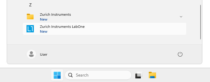
The LabOne User Interface start-up link can be found under the Windows
10/11 Start Menu. As
shown in Figure 2, click on
Start Menu → Zurich Instruments LabOne. This will open the User
Interface in a new tab in your default web browser and start the LabOne
Data Server and LabOne Web Server programs in the background. A detailed
description of the software architecture is found in LabOne Software
Architecture.
LabOne is an HTML5 browser-based program. This simply means that the user interface runs in a web browser and that a connection using a mobile device is also possible; simply specify the IP address (and port 8006) of the PC running the user interface.
Note
By creating a shortcut to Google Chrome on your desktop with the Target
path\to\chrome.exe -app=http://127.0.0.1:8006 set in Properties you
can run the LabOne User Interface in Chrome in application mode, which
improves the user experience by removing the unnecessary browser
controls.
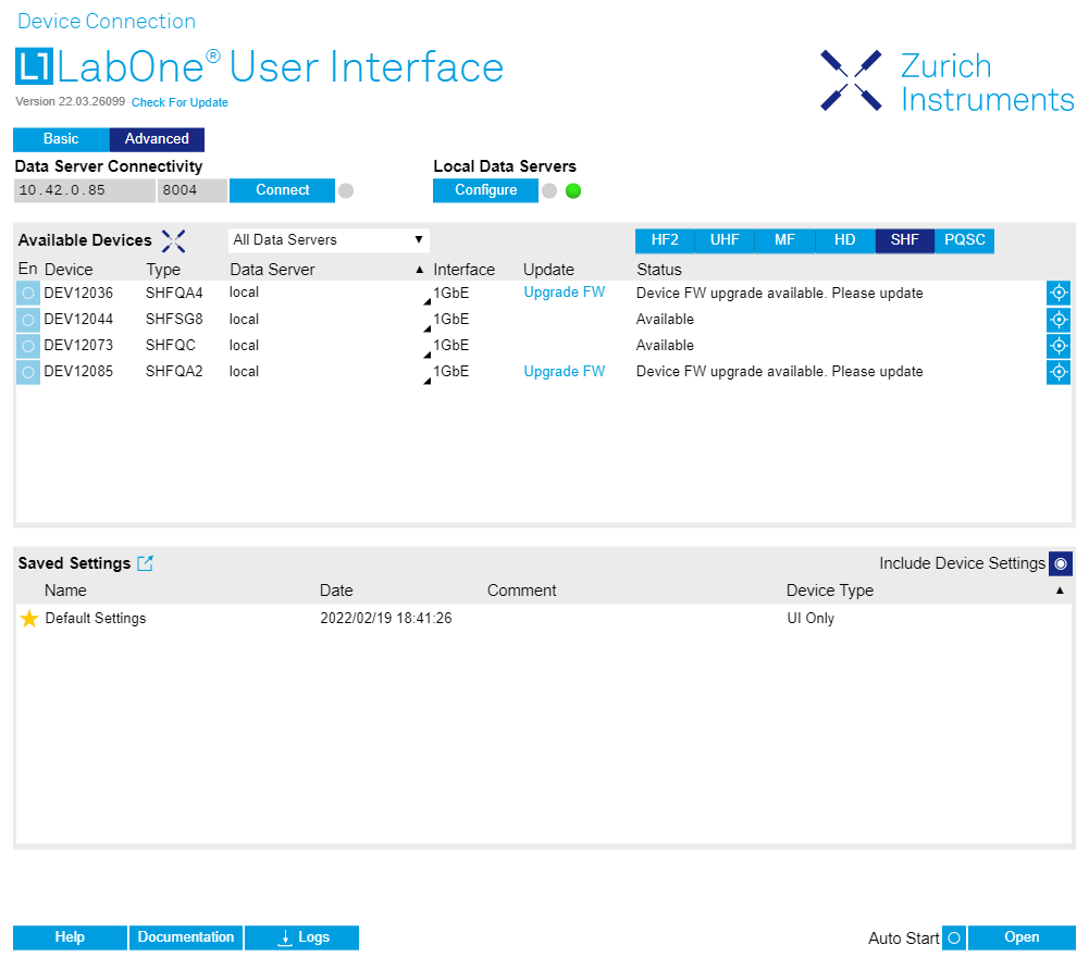
After starting LabOne, the Device Connection dialog Figure 3 is shown to select the device for the session. The term "session" is used for an active connection between the user interface and the device. Such a session is defined by device settings and user interface settings. Several sessions can be started in parallel. The sessions run on a shared LabOne Web Server. A detailed description of the software architecture can be found in the LabOne Software Architecture.

The Device Connection dialog opens in the Basic view by default. In this
view, all devices that are available for connection are represented by
an icon with serial number and status information. If required, a button
appears on the icon to perform a firmware upgrade. Otherwise, the device
can be connected by a double click on the icon, or a click on the  button at the bottom right of the dialog.
In some cases it’s useful to switch to the Advanced view of the Device Connection dialog by clicking on the "Advanced" button. The Advanced view offers the possibility to select custom device and UI settings for the new session and gives further connectivity options that are particularly useful for multi-instrument setups.
The Advanced view consists of three parts:
- Data Server Connectivity
- Available Devices
- Saved Settings
The Available Devices table has a display filter, usually set to Default Data Server, that is accessible by a drop-down menu in the header row of the table. When changing this to Local Data Servers, the Available Devices table will show only connections via the Data Server on the host PC and will contain all instruments directly connected to the host PC via USB or to the local network via 1GbE. When using the All Data Servers filter, connections via Data Servers running on other PCs in the network also become accessible. Once your instrument appears in the Available Devices table, perform the following steps to start a new session:
-
Select an instrument in the Available Devices table.
-
Select a setting file in the Saved Settings list unless you would like to use the Default Settings.
-
Start the session by clicking on
Note
By default, opening a new session will only load the UI settings (such as plot ranges), but not the device settings (such as signal amplitude) from the saved settings file. In order to include the device settings, enable the Include Device Settings checkbox. Note that this can affect existing sessions since the device settings are shared between them.
Note
In case devices from other Zurich Instruments series (UHF, HF2, MF, HDAWG, PQSC, GHF, or SHF) are used in parallel, the list in Available Devices section can contain those as well.
The following sections describe the functionality of the Device Connection dialog in detail.
Data Server Connectivity
The Device Connection dialog represents a Web Server. However, on start-up the Web Server is not yet connected to a LabOne Data Server. With the Connect/Disconnect button the connection to a Data Server can be opened and closed.
This functionality can usually be ignored when working with a single SHFQC+ Instrument and a single host computer. Data Server Connectivity is important for users operating their instruments from a remote PC, i.e., from a PC different to the PC on which the Data Server is running or for users working with multiple instruments. The Data Server Connectivity function then gives the freedom to connect the Web Server to one of several accessible Data Servers. This includes Data Servers running on remote computers, and also Data Servers running on an MF Series instrument.
In order to
work with a UHF, HF2, HDAWG, PQSC, GHF, or SHF instrument remotely,
proceed as follows. On the computer directly connected to the instrument
(Computer 1) open a User Interface session and change the Connectivity
setting in the Config tab to "From Everywhere". On the remote computer
(Computer 2), open the Device Connection dialog by starting up the
LabOne User Interface and then go to the Advanced view by clicking on
 on the top left of the dialog. Change the display filter from Default
Data Server to All Data Servers by opening the drop-down menu in the
header row of the Available Devices table. This will make the Instrument
connected to Computer 1 visible in the list. Select the device and
connect to the remote Data Server by clicking on
on the top left of the dialog. Change the display filter from Default
Data Server to All Data Servers by opening the drop-down menu in the
header row of the Available Devices table. This will make the Instrument
connected to Computer 1 visible in the list. Select the device and
connect to the remote Data Server by clicking on  .
Then start the User Interface as described above.
.
Then start the User Interface as described above.
Note
When using the filter "All Data Servers", take great care to connect to the right instrument, especially in larger local networks. Always identify your instrument based on its serial number in the form DEV0000, which can be found on the instrument back panel.
Available Devices
The Available Devices table gives an overview of the visible devices. A
device is ready for use if either marked free or connected. The first
column of the list holds the Enable button controlling the
connection between the device and a Data Server. This button is greyed
out until a Data Server is connected to the LabOne Web Server using the
button. If a device is connected to a Data Server, no other Data Server
running on another PC can access this device.
The second column indicates the serial number and the third column shows the instrument type. The fourth column shows the host name of the LabOne Data Server controlling the device. The next column shows the interface type. For SHFQC+ Instruments the interfaces USB or 1GbE are available and are listed if physically connected. The LabOne Data Server will scan for the available devices and interfaces every second. If a device has just been switched on or physically connected it may take up to 20 s before it becomes visible to the LabOne Data Server.
| Available | The device is not in use by any LabOne Data Server and can be connected by clicking the Enable button. Alternatively, a session can also be started by clicking on the Open button, without prior connection. |
| In use by | The device is in use by a LabOne Data Server. As a consequence the device cannot be accessed by the specified interface. To access the device a disconnect is needed. The additional message "FW upgrade available" or "FW downgrade available" may also be displayed in this state. |
| Connected | The device is connected to a LabOne Data Server, either on the same PC (indicated as local) or on a remote PC (indicated by its IP address). The user can start a session to work with that device. |
| Device FW upgrade required | The firmware is out of date and must be upgraded before the device can be used. Please first upgrade the firmware by clicking on the Upgrade FW button as described in Software Update. |
| Device FW upgrade available. Please update | The firmware is out of date but the device can still be used. It is highly recommended to upgrade the firmware by clicking on the Upgrade FW button as described in Software Update. |
| Device FW downgrade available | The firmware of the device is newer than the version supplied with the installed LabOne software. This could be due to reverting to an earlier LabOne version. The device can still be used but it is also possible to downgrade to the older firmware version if for any reason this is necessary. Click on the Downgrade FW button to downgrade the firmware. It is strongly advised to upgrade LabOne instead of downgrading the firmware. |
| Device FW upgrade required. Please use USB firmware upgrade utility | The firmware of UHFLI/UHFQA is too old to be updated from the Device Connection dialog. Please first upgrade the firmware using the USB Firmware Upgrade Utility provided with LabOne software. |
| Device not yet ready | The device is visible and starting up. When the device is ready it will be flagged as Available. |
Saved Settings
Settings files can contain both UI and device settings. UI settings control the structure of the LabOne User Interface, e.g. the position and ordering of opened tabs. Device settings specify the set-up of a device. The device settings persist on the device until the next power cycle or until overwritten by loading another settings file.
The columns are described in Table 2. The table rows can be sorted by clicking on the column header that should be sorted. The default sorting is by time. Therefore, the most recent settings are found on top. Sorting by the favorite marker or setting file name may be useful as well.
 |
Allows favorite settings files to be grouped together. By activating the stars adjacent to a settings file and clicking on the column heading, the chosen files will be grouped together at the top or bottom of the list accordingly. The favorite marker is saved to the settings file. When the LabOne user interface is started next time, the row will be marked as favorite again. |
| Name | The name of the settings file. In the file system, the file name has the extension .md. |
| Date | The date and time the settings file was last written. |
| Comment | Allows a comment to be stored in the settings file. By clicking on the comment field a text can be typed in which is subsequently stored in the settings file. This comment is useful to describe the specific conditions of a measurement. |
| Device Type | The instrument type with which this settings file was saved. |
Special Settings Files
Certain file names have the prefix "last_session_". Such files are created automatically by the LabOne Web Server when a session is terminated either explicitly by the user, or under critical error conditions, and save the current UI and device settings. The prefix is prepended to the name of the most recently used settings file. This allows any unsaved changes to be recovered upon starting a new session.
If a user loads such a last session settings file the "last_session_" prefix will be cut away from the file name. Otherwise, there is a risk that an auto-save will overwrite a setting which was saved explicitly by the user.
The settings file with the name "Default Settings" contains the default UI settings. See button description in Table 3.
| Open | The settings contained in the selected settings file will be loaded. The button "Include Device Settings" controls whether only UI settings are loaded, or if device settings are included. |
| Include Device Settings | Controls which part of the selected settings file is loaded upon clicking on Open. If enabled, both the device and the UI settings are loaded. |
| Auto Start | Skips the session dialog at start-up if selected device is available. The default UI settings will be loaded with unchanged device settings. |
Note
The user setting files are saved to an application-specific folder in the directory structure. The best way to manage these files is using the File Manager tab.
Note
The factory default UI settings can be customized by saving a file with the name "default_ui" in the Config tab once the LabOne session has been started and the desired UI setup has been established. To use factory defaults again, the "default_ui" file must be removed from the user setting directory using the File Manager tab.
Note
Double clicking on a device row in the Available Devices table is a quick way of starting the default LabOne UI. This action is equivalent to selecting the desired device and clicking the Open button.
Double clicking on a row in the Saved Settings table is a quick way of loading the LabOne UI with those UI settings and, depending on the "Include Device Settings" checkbox, device settings. This action is equivalent to selecting the desired settings file and clicking the Open button.
Tray Icon
When LabOne is started, a tray icon appears by default in the bottom right corner of the screen, as shown in the figure below. By right-clicking on the icon, a new web server session can be opened quickly, or the LabOne Web and Data Servers can be stopped by clicking on Exit. Double-clicking the icon also opens a new web server session, which is useful when setting up a connection to multiple instruments, for example.
Messages
The LabOne Web Server will show additional messages in case of a missing component or a failure condition. These messages display information about the failure condition. The following paragraphs list these messages and give more information on the user actions needed to resolve the problem.
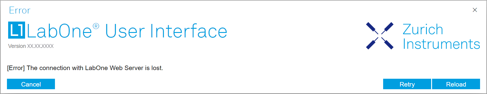
Lost Connection to the LabOne Web Server
In this case the browser is no longer able to connect to the LabOne Web Server. This can happen if the Web Server and Data Server run on different PCs and a network connection is interrupted. As long as the Web Server is running and the session did not yet time out, it is possible to just attach to the existing session and continue. Thus, within about 15 seconds it is possible with Retry to recover the old session connection. The Reload button opens the Device Connection dialog shown in Figure 3. The figure below shows an example of the Connection Lost dialog.
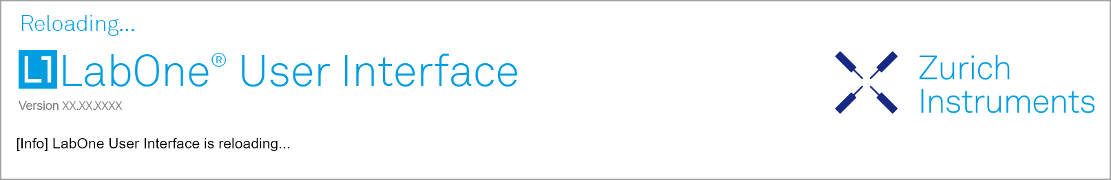
Reloading...
If a session error cannot be handled, the LabOne Web Server will restart to show a new Device Connection dialog as shown in Figure 3. During the restart a window is displayed indicating that the LabOne User Interface will reload. If reloading does not happen the same effect can be triggered by pressing F5 on the keyboard. The figure below shows an example of this dialog.
No Device Discovered
An empty "Available Devices" table means that no devices were discovered. This can mean that no LabOne Data Server is running, or that it is running but failed to detect any devices. The device may be switched off or the interface connection fails. For more information on the interface between device and PC see Visibility and Connection. The figure below shows an example of this dialog.

No Device Available
If all the devices in the "Available Devices" table are shown grayed, this indicates that they are either in use by another Data Server, or need a firmware upgrade. For firmware upgrade see Software Update. If all the devices are in use, access is not possible until a connection is relinquished by another Data Server.
Visibility and Connection
There are several ways to connect the instrument to a host computer. The device can either be connected by Universal Serial Bus (USB) or by 1 Gbit/s Ethernet (1GbE). The USB connection is a point-to-point connection between the device and the PC on which the Data Server runs. The 1GbE connection can be a point-to-point connection or an integration of the device into the local network (LAN). Depending on the network configuration and the installed network card, one or the other connectivity is better suited.
If an instrument is connected to a network, it can be accessed from multiple host computers. To manage the access to the instrument, there are two different connectivity states: visible and connected. It is important to distinguish if an instrument is just physically connected over 1GbE or actively controlled by the LabOne Data Server. In the first case the instrument is visible to the LabOne Data Server. In the second case the instrument is logically connected.
Connectivity Example shows some examples of possible configurations of computer-to-instrument connectivity.
- Data Server on PC 1 is connected to device 1 (USB) and device 2 (USB).
- Data Server on PC 2 is connected to device 4 (TCP/IP).
- Data Server on PC 3 is connected to device 5.
- The device 3 is free and visible to PC 1 and PC 2 over TCP/IP.
- Devices 2 and 4 are physically connected by TCP/IP and USB interface. Only one interface is logically connected to the Data Server.

Visible Instruments
An instrument is visible if the Data Server can identify it. On a TCP/IP network, several PCs running a Data Server will detect the same instrument as visible, i.e., discover it. If a device is discovered, the LabOne Data Server can initiate a connection to access the instrument. Only a single Data Server can be connected to an instrument at a time.
Connected Instrument
Once connected to an instrument, the Data Server has exclusive access to that instrument. If another Data Server from another PC already has an active connection to the instrument, the instrument is still visible but cannot be connected.
Although a Data Server has exclusive access to a connected instrument, the Data Server can have multiple clients. Because of this, multiple browser and API sessions can access the instrument simultaneously.
USB Connectivity
To control the device over USB, connect the instrument with the supplied USB cable to the PC on which the LabOne Software is installed. The USB driver needed for controlling the instrument is included in the LabOne Installer package. Ensure that the instrument uses the latest firmware. The software will automatically use the USB interface for controlling the device if available. If the USB connection is not available, the 1GbE connection may be selected. It is possible to enforce or exclude a specific interface connection.
1GbE Connectivity
There are three methods for connecting to the device via 1GbE:
- Multicast DHCP
- Multicast point-to-point (P2P)
- Static Device IP
Multicast DHCP is the simplest and preferred connection method. Other connection methods can become necessary when using network configurations that conflict with local policies.
Multicast DHCP
The most straightforward TCP/IP connection method is to rely on a network configuration to recognize the instrument. When connecting the instrument to a local area network (LAN), the DHCP server will assign an IP address to the instrument like to any PC in the network. In case of restricted networks, the network administrator may be required to register the device on the network by means of the MAC address. The MAC address is indicated on the back panel of the instrument. The LabOne Data Server will detect the device in the network by means of a multicast.
If the network configuration does not support multicast, or if the host
computer has other network cards installed, it is necessary to use a
static IP setup as described below. The instrument is configured to
accept the IP address from the DHCP server, or to fall back to the IP
address 192.168.1.10 if it does not get the address from the DHCP
server.
Requirements:
- Network supports multicast
Multicast Point-to-Point
Setting up a point-to-point (P2P) network consisting only of the host computer and the instrument avoids problems related to special network policies. Since it is nonetheless necessary to stay connected to the internet, it is recommended to install two network cards in the computer, one of which is used for internet connectivity, the other can be used for connecting to the instrument. Alternatively, internet connectivity can be established via wireless LAN.
In such a P2P network the IP address of the host computer needs to be set to a static value, whereas the IP address of the device can be left dynamic.
-
Connect the 1GbE port of the network card that is dedicated for instrument connectivity directly to the 1GbE port of the instrument
-
Set this network card to static IP in TCP/IPv4 using the address
192.168.1.n, where n=[2..9] and the mask255.255.255.0. (On Windows go toControl Panel → Internet Options → Network and Internet → Network and Sharing Center → Local Area Connection → Properties).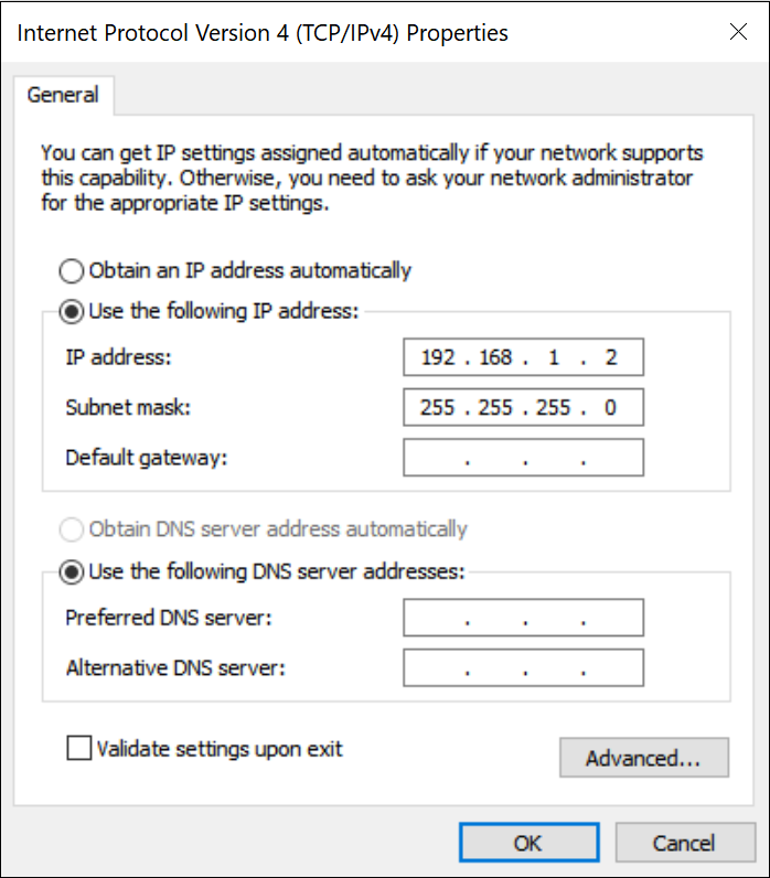
Figure 10: Static IP configuration for the host computer -
Start up the LabOne User Interface normally. If your instrument does not show in the list of Available Devices, the reason may be that your network card does not support multicast. In that case, see Static Device IP.
Requirements:
- Two network cards needed for additional connection to internet
- Network card of PC supports multicast
- Network card connected to the device must be in static IP4 configuration
Note
A power cycle of the instrument is required if it was previously connected to a network that provided an IP address to the instrument.
Note
Only IP v4 is currently supported. There is no support for IP v6.
Note
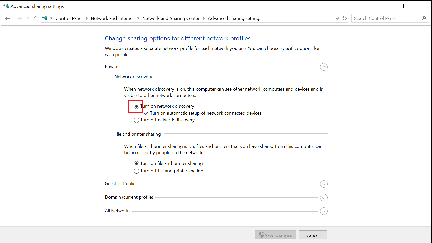
If the instrument is detected by LabOne but the connection can not be established, the reason can be the firewall blocking the connection. It is then recommended to change the P2P connection from Public to Private. On Windows this is achieved by turning on network discovery in the Private tab of the network’s advanced sharing settings as shown in the figure below.
Warning
Changing the IP settings of your network adapters manually can interfere with its later use, as it cannot be used anymore for network connectivity until it is configured again for dynamic IP.

Static Device IP
Although it is highly recommended to use dynamic IP assignment method in the host network of the instrument, there may be cases where the user wants to assign a static IP to the instrument. For instance, when the host network only contains Ethernet switches and hubs but no Ethernet routers are included, there is no DHCP server to dynamically assign an IP to the instrument. It is still advised to add an Ethernet router to the network and benefit from dynamic IP assignment; however, if a router is not available, the instrument can be configured to work with a static IP.
Note that the static IP assigned to the instrument must be within the
same range of the IP assigned to the host computer. Whether the host
computer’s IP is assigned statically or by a fallback mechanism, one can
find this IP by running the command ipconfig or ipconfig/all in the
operating system’s terminal. As an example, Figure 13 shows the outcome of
running ipconfig in the terminal.
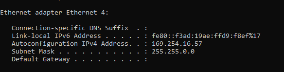
It shows the network adapter of the host computer can be reached via the
IP 169.254.16.57 and it uses a subnet mask of 255.255.0.0. To make
sure that the instrument is visible to this computer, one needs to
assign a static IP of the form 169.254.x.x and the same subnet mask to
the instrument. To do so, the user should follow the instructions below.
-
Attach the instrument using an Ethernet cable to the network where the user’s computer is hosted.
-
Attach the instrument via a USB cable to the host computer and switch it on.
-
Open the LabOne user interface (UI) and connect to the instrument via USB.
-
Open the "Device" tab of the LabOne UI and locate the "Communication" section as shown in Configuration of static IP in LabOne UI.
-
Write down the desired static IP, e.g.
169.254.16.20, into the numeric field "IPv4 Address". -
Add the same subnet mask as the host computer, e.g.
255.255.0.0to the numeric field "IPv4 Mask". -
You can leave the field "Gateway" as
0.0.0.0or change to be similar to the IP address but ending with1, e.g.169.254.16.1. -
Enable the radio button for "Static IP".
-
Press the button "Program" to save the new settings to the instruments.
-
Power cycle the instrument and remove the USB cable. The instrument should be visible to LabOne via Ethernet connection.

To make sure the IP assignment is done properly, one can use the command
ping to check if the instrument can be reached through the network
using its IP address. Figure 15 shows the outcome of
ping when the instrument is visible via the IP 169.254.16.20.

If set properly according to the instructions above, the instrument will use the same static IP configurations after each power cycle.
Fallback Device IP
When configured to a dynamic address, but no DHCP server is present in the network, e.g., device connected directly to a PC, the instrument falls back on an IP address in the local link IP range that is 169.254.x.x. If the host computer has also an IP address within the same range, the instrument becomes visible to the LabOne data server running on the host computer. This way, there is no need to go through the process described above to assign a static IP to the instrument.