Digital Modulation Tab
The Digital Modulation tab can be used to configure the digital oscillators, as well as the settings used to modulate pulse sequences and generate sinusoidal signals. It is available on all SHFQC+ instruments.
Features
- Sine generator configuration: frequency, oscillator select, harmonic, phase, amplitude
- Gain settings for upper- or lower-sideband modulation
- Enable pulse modulation or continuous signal output
Description
| Control/Tool | Option/Range | Description |
|---|---|---|
| Mod | Access to all the settings of the digital modulation. |
The Digital Modulation tab (see Figure 1) is divided into three sections: Oscillators, Sine Generators, and Waveform Generators.
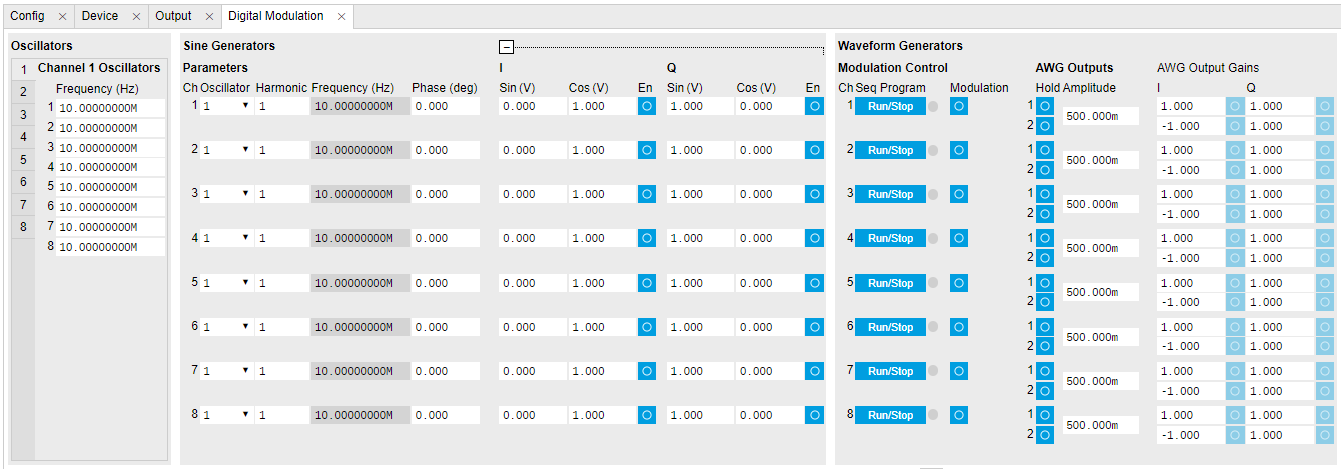
The purpose of the Digital Modulation tab is to configure the digital sine generator of each SG channel, to enable the modulation (i.e. multiplication) or addition of sinusoidal and AWG signals. The tabular layout of the tab provides a quick overview of the status of the different channels of the instrument.
Conceptually, the tab is laid out as follows: The Oscillators section contains the frequencies of the eight digital oscillators for each channel. The Sine Generators section contains settings such as phase and harmonic for the sine generator of each channel, as well as settings for generating sinusoidal signal outputs. The Waveform Generators section configures how the sine generator is used to modulate the AWG signals. The signal on a given output can be a multiplication, or addition, or both, of AWG and sinusoidal signals, depending which modulation modes are enabled.
The individual sinusoidal and AWG signals are configured in the Sine Generators and Waveform Generators sections, respectively. For an example of how to generate a continuous, sinusoidal signal on a given channel, the see Basic Sine Generation Tutorial. For an example of how to use the sine generator to modulate a pulse sequence from the AWG, see the Digital Modulation Tutorial.
The gain settings in the Waveform Generators and the Sine Generators sections are graphically grouped in pairs, and each pair is associated with an I or Q input to the DAC. For the Sine Generators section, the I and Q pairs are further separated into Sin and Cos terms. In the Waveform Generators section, the I and Q pairs of gain settings. In both cases, the default settings are chosen to generate an upper sideband signal when using a positive oscillator frequency. For a more detailed explanation of how these gain settings are used in generating signals, see the Digital Modulation Tutorial.
Functional Elements
| Control/Tool | Option/Range | Description |
|---|---|---|
| SG Channels | Select SG Channel to display corresponding set of oscillator frequencies. | |
| Frequency (Hz) | Oscillator frequency. | |
| Oscillator Select | Selection of the oscillator used for the generated sine signal. | |
| Harmonic | Multiplies the oscillator's reference frequency with the integer factor defined by this field. | |
| Frequency (Hz) | Frequency of the selected oscillator. | |
| Phase Shift (deg) | Sets the phase of the sine signal. | |
| I Sin Amplitude | Sets the amplitude of the sine signal sent to the I input of the digital mixer. | |
| I Cos Amplitude | Sets the amplitude of the cosine signal sent to the I input of the digital mixer. | |
| I Enable | ON / OFF | Enables the I input of the digital mixer. |
| Q Sin Amplitude | Sets the amplitude of the sine signal sent to the Q input of the digital mixer. | |
| Q Cos Amplitude | Sets the amplitude of the cosine signal sent to the Q input of the digital mixer. | |
| Q Enable | ON / OFF | Enables the Q input of the digital mixer. |
| Run |  |
Runs the AWG sequencer. |
| Sequencer Status | off/green/yellow/red | Displays the status of the sequencer on the instrument. Off: Ready, not running. Green: Running, not waiting for any trigger event. Yellow: Running, waiting for a trigger event. Red: Not ready (e.g., pending elf upload, no elf uploaded). |
| Modulation Enable | ON / OFF | Enables digital modulation of the waveforms generated by the AWG. |
| Hold | ON / OFF | Keep the last sample (constant) on the outputs even after the waveform program finishes. It is recommended to use only AWG waveforms with lengths equal to a multiple of 16 together with this functionality. Waveforms with other lengths are automatically padded with zeros at the end by the AWG compiler. The status of the hold node is checked only when the AWG is enabled. If hold is disabled after enabling the AWG or when the AWG is not running, AWG output values will still be held. |
| AWG Output Amplitude | Sets the amplitude of the AWG output. | |
| Delay (s) | This value adds a delay to both the signal and trigger/marker outputs. | |
| AWG Output Gain Amplitude | Sets the amplitude scaling factor of the given AWG channel. The amplitude is a dimensionless scaling factor applied to the digital signal. | |
| AWG Output Gain Enable | ON / OFF | Indicates the routing of the AWG signal (row) to the digital mixer inputs (column). |