Multi-Channel Playback
Note
This tutorial is applicable to all HDAWG Instruments. The number of available signal channels depends on the model (HDAWG4 or HDAWG8).
Goals and Requirements
The goal of this tutorial is to demonstrate multi-channel waveform playback with the AWG. In order to visualize the multi-channel signals, an oscilloscope with sufficient bandwidth and channel number is required.
Preparation
Connect the cables as illustrated below. Make sure that the instrument is powered on and connected by Ethernet to your local area network (LAN) where the host computer resides. After starting LabOne, the default web browser opens with the LabOne graphical user interface.

The tutorial can be started with the default instrument configuration (e.g. after a power cycle) and the default user interface settings (e.g. as is after pressing F5 in the browser).
Sequencer synchronization
Using the sequencer synchronization feature of the HDAWG, we can generate tightly synchronized, multi-channel signals. In the previous tutorial, we used one single sequencer, and we wrote sequence programs for dual-channel playback. Here we show an example of a 4-channel sequence program using two sequencers. To this end, we enable synchronization between the first two AWG cores, so that they start at the same time. We monitor the AWG signal using four channels of an external scope. The following tables summarize the settings to enable the HDAWG Wave outputs, to enable multi-core synchronization, and to configure the external scope.
| Tab | Sub-tab | Section | # | Label | Setting / Value / State |
|---|---|---|---|---|---|
| Output | Waveform Generators | 1-2 | Sync | ON | |
| Output | Wave Outputs | 1-4 | Enable | ON |
| Scope Setting | Value / State |
|---|---|
| Ch1-4 enable | ON |
| Ch1-4 range | 0.2 V/div |
| Timebase | 500 ns/div |
| Trigger source | Ch1 |
| Trigger level | 100 mV |
| Run / Stop | ON |
The step from a dual-channel to a four-channel sequence is achieved by
using two sequencers instead of one, each one controlling its two wave outputs.
The following sequence program generates a signal with
4 simultaneous pulses with different amplitudes. The setTrigger
instructions can optionally be used to trigger the scope if the latter
has an auxiliary trigger input as shown in
Basic Waveform Playback. Upload and run this program to the sequencer 1:
// Waveforms definition
wave w = gauss(8000, 4000, 1000);
wave w1 = 1.0*w;
wave w2 = 0.5*w;

// Playback
while (true) {
  playWave(1,w1, 2,w2);
  setTrigger(1); setTrigger(0);
  playZero(80000);
}
and this program to sequencer 2:
// Waveforms definition
wave w = gauss(8000, 4000, 1000);
wave w3 = -0.5*w;
wave w4 = -1.0*w;

// Playback
while (true) {
  playWave(1,w3, 2,w4);
  playZero(80000);
}
Note
In the second sequence, the signal routing control indices are 1 and 2, even if we refer to the wave output channels 3 and 4. That's because these indices are relative to the AWG core itself, and not the absolute wave output channel indices. See Signal routing control for more details.
Note
You can notice that the setTrigger have been positioned after the first playWave command. This is necessary because otherwise the second sequencer will start its playback a bit earlier than the first. In this way, both AWGs will start playing at the same time, and the first will toggle the marker output at almost the same time as the waveform start. See
Generating Trigger and Marker Outputs with the AWG for more details.
Finally, enable both sequencers by clicking on their "Run" buttons, as shown in Table 3 in no particular order. As a consequence of the sync setting, you will notice that after enabling the first sequencer and before enabling the second, the status LED will turn yellow, meaning that it will wait for the other sequencer to be started. Only once both sequencers are started will the two status LEDs turn green indicating they are running.
| Tab | Sub-tab | Section | # | Label | Setting / Value / State |
|---|---|---|---|---|---|
| Output | Waveform Generators | 1-2 | Seq Program | Run |
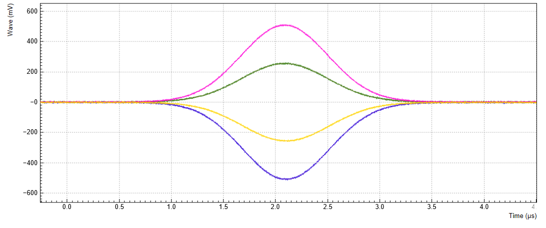
Figure 2 shows the signal generated with this program and measured with the scope.
On HDAWGs with 8 channels, this can be extended to synchronize up to four sequencers and eight channels.
Multiple pulses synchronization
When dealing with more complex sequences, it's important to define the playback such that the sequencers stay in sync. The best way is to make sure that each sequencer plays the same amount of samples as the other ones, regardless of the waveform content. When a AWG core is not supposed to produce any signal, it's recommended to use a playZero command.
For example, let's generate a sample sequence as follow:

We can divide the sequence vertically at the points where at least one channel starts or stops playing a waveform. We can then used a playWave/playZero command for each section.
The first AWG core will need to be programmed with the following sequence:
//Lengths of sections
const L1 = 384;
const L2 = 128;
const L3 = 512;
const L4 = 128;
const L5 = 16000;

// Waveforms definition
wave wI_1 = 1.0*gauss(L1, L1/2, L1/8);
wave wI_2 = 0.8*gauss(L1, L1/2, L1/8);

// Playback
playWave(1,wI_1, 2,wI_2); //section I
setTrigger(1); setTrigger(0);
playZero(L2);             //section II
playZero(L3);             //section III
playZero(L4);             //section IV
playZero(L5);             //section V
while the second will need this sequence
//Lengths of sections
const L1 = 384;
const L2 = 128;
const L3 = 512;
const L4 = 128;
const L5 = 16000;

// Waveforms definition
wave wII_3 = 0.6*ones(L2);
wave wIII_4 = -0.5*ones(L3);
wave wIV_3 = 0.6*ones(L4);

// Playback
playZero(L1);             //section I
playWave(1,wII_3);        //section II
playWave(1,"", 2,wIII_4); //section III
playWave(1,wIV_3);        //section IV
playZero(L5);             //section V
Note
Consecutive playZero commands can be collapsed into a single one.
For example, in the example above for the first sequencer,
they can be replaced by a single playZero(L2+L3+L4+L5).
That will improve instruction memory consumption.
Note
The use of the playZero(n) instruction is strongly encouraged in
replacement of a playback of a zero-valued waveform, e.g.
playWave(zeros(n)). Both instructions will result in the same output,
but playZero consumes no waveform memory. In addition to avoiding the
limit of number of waveforms, it allows you to greatly reduce waveform
upload time to the instrument. Moreover, playZero uses a single assembly instruction.
Note
The instruction playZero(n) can replace the instruction wait(m) with
n=m*8 in most cases. It has the advantage of behaving equivalently to
a playWave instruction.