DIO Tab
The DIO tab provides access to the settings and controls of the digital I/O as well as the Marker outputs and Trigger inputs and is available on all HDAWG instruments.
Features
- Monitor and control of digital I/O connectors
- Control settings for marker outputs and trigger inputs
Description
The DIO tab is the main panel to control the digital inputs and outputs as well as the trigger levels . Whenever the tab is closed or an additional one of the same type is needed, clicking the following icon will open a new instance of the tab.
| Control/Tool | Option/Range | Description |
|---|---|---|
| DIO | Gives access to all controls relevant for the digital inputs and outputs including DIO, Trigger Inputs, Trigger Outputs, and Marker Outputs. |
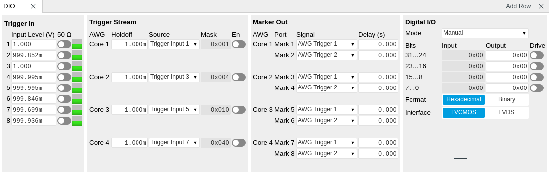
The Trigger In section shows the settings for the 4 or 8 Trig inputs on the front panel. The LED status indicator helps in monitoring the input signal state and selecting the threshold. The Trigger Stream section allows the user to control streaming of trigger signals to the computer and monitor them in the Plotter tool over time. The Marker Out section allows assigning internal marker bits to the 4 or 8 Mark outputs on the front panel. Alternatively, the outputs can be set to static high or low values.
The Digital I/O section provides numerical monitors to observe the states of the digital inputs and outputs on the DIO port on the back of the instrument. Moreover, with the values set in the Output column and the Drive button activated the states can also be actively set in different numerical formats. The mode selector allow the user to select if the DIO port is controlled manually by the user, by the AWG sequencer or if the HDAWG is connected to a PQSC by the ZSync port. In the latter case, the DIO port can be used exclusively to connect a UHFQA (see the UHFQA user manual).
Important
The DIO port is fully functional when the sample rate is exactly 2.4 GSa/s.
Functional Elements
| Control/Tool | Option/Range | Description |
|---|---|---|
| DIO mode | Select DIO mode | |
| Manual | Enables manual control of the DIO output bits. | |
| AWG Sequencer | Enables setting the DIO output values by AWG sequencer commands and forwards DIO input values to the AWG sequencer. The DIO interface operates at a clock frequency of 150 MHz. | |
| DIO Codeword | Enables setting the DIO output values by AWG sequencer commands and forwards DIO input values to the AWG sequencer. This mode is equivalent to the mode AWG Sequencer, except for the DIO interface clock frequency which is set to 50 MHz. | |
| QCCS | Enables setting the DIO output values by the ZSync input values. Forwards the ZSync input values to the AWG sequencer. Forwards the DIO input values to the ZSync output. Select this mode when the instrument is connected via ZSync to a PQSC. | |
| QA Result Overflow | grey/yellow/red | Red: present overflow condition on the DIO interface during readout. Yellow: indicates an overflow occurred in the past. An overflow can happen if readouts are triggered faster than the maximum possible data-rate of the DIO interface. |
| DIO bits | label | Partitioning of the 32 bits of the DIO into 4 buses of 8 bits each. Each bus can be used as an input or output. |
| DIO input | numeric value in either Hex or Binary format | Current digital values at the DIO input port. |
| DIO output | numeric value in either hexadecimal or binary format | Digital output values. Enable drive to apply the signals to the output. |
| DIO drive | ON / OFF | When on, the corresponding 8-bit bus is in output mode. When off, it is in input mode. |
| Format | Select DIO view format. | |
| Hexadecimal | DIO view format is hexadecimal. | |
| Binary | DIO view format is binary. | |
| Clock | Select DIO internal or external clocking. | |
| Interface | Selects the interface standard to use on the 32-bit DIO interface. This setting is persistent across device reboots. Choose LVCMOS if connecting to a UHFQA through the DIO interface. | |
| LVCMOS | A single-ended, 3.3V CMOS interface is used. | |
| LVDS | A differential, LVDS compatible interface is used. | |
| Enable | ON / OFF | Enables trigger streaming. |
| Holdoff Time | time in seconds | Sets the holdoff time of the trigger unit. |
| Trigger Source | Selects a trigger source for the stream. The mask is bit encoded where bit 0..7 are the input triggers and bit 8..11 are AWG triggers. The "Mask" setting allows for an arbitrary combination of trigger sources using the bit encoding in the "Mask" field. | |
| Mask Triggers | Masks triggers for the current stream. Only enabled if "Mask" is selected as trigger stream source. The mask is bit encoded where bit 0..7 are the input triggers and bit 8..11 are AWG triggers. | |
| Trigger level | -10 V to 10 V | Trigger voltage level at which the trigger input toggles between low and high. Use 50% amplitude for digital input and consider the trigger hysteresis. |
| 50 Ω | 50 Ω/1 kΩ | Trigger input impedance: When on, the trigger input impedance is 50 Ω, when off 1 kΩ. |
| Trigger Input Low status | Indicates the current low level trigger state. | |
| Off | A low state is not being triggered. | |
| On | A low state is being triggered. | |
| Trigger Input High status | Indicates the current high level trigger state. | |
| Off | A high state is not being triggered. | |
| On | A high state is being triggered. | |
| Marker output signal | Select the signal assigned to the marker output. | |
| AWG Trigger 1 | Trigger output is assigned to one of the AWG Trigger channels controlled by AWG sequencer commands. | |
| AWG Trigger 2 | Trigger output is assigned to one of the AWG Trigger channels controlled by AWG sequencer commands. | |
| AWG Trigger 3 | Trigger output is assigned to one of the AWG Trigger channels controlled by AWG sequencer commands. | |
| AWG Trigger 4 | Trigger output is assigned to one of the AWG Trigger channels controlled by AWG sequencer commands. | |
| Output 1 Marker 1 | Output is assigned to Output 1 Marker 1. | |
| Output 1 Marker 2 | Output is assigned to Output 1 Marker 2. | |
| Output 2 Marker 1 | Output is assigned to Output 2 Marker 1. | |
| Output 2 Marker 2 | Output is assigned to Output 2 Marker 2. | |
| Trigger Input 1 | Output is assigned to Trigger Input 1. | |
| Trigger Input 2 | Output is assigned to Trigger Input 2. | |
| Trigger Input 3 | Output is assigned to Trigger Input 3. | |
| Trigger Input 4 | Output is assigned to Trigger Input 4. | |
| Trigger Input 5 | Output is assigned to Trigger Input 5. | |
| Trigger Input 6 | Output is assigned to Trigger Input 6. | |
| Trigger Input 7 | Output is assigned to Trigger Input 7. | |
| Trigger Input 8 | Output is assigned to Trigger Input 8. | |
| High | Output is set to high. | |
| Low | Output is set to low. | |
| Delay (s) | This delay adds an offset that acts only on the trigger/marker output. The total delay to the trigger/marker output is the sum of this value and the value of the output delay node. | |
| Delay | Approximately -15 ns to 30 ns (depends on sampling clock frequency) | Controls the fine delay of the Marker output, range approximately -15 ns to 30 ns (depends on sampling clock frequency) |