Device Tab
The Device tab is the main settings tab for the connected instrument and is available on all HDAWG instruments.
Features
- Option and upgrade management
- External clock reference settings and ZSync connectivity
- Dynamic layout for 1x8, 2x4, 4x2 channel grouping
- Instrument reset
- Instrument connectivity parameters
- Device monitor
Description
The Device tab serves mainly as a control panel for all settings specific to the instrument that is controlled by LabOne in this particular session. Whenever the tab is closed or an additional one of the same type is needed, clicking the following icon will open a new instance of the tab.
| Control/Tool | Option/Range | Description |
|---|---|---|
| Device | Provides instrument specific settings. |
The Device tab (see Figure 1) is divided into five sections: general instrument information, configuration, communication parameters, device presets, and a device monitor.
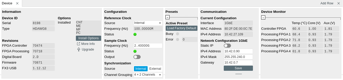
The Information section provides details about the instrument hardware and indicates the installed upgrade options. This is also the place where new options can be added by entering the provided option key.
The Configuration section allows one to control the reference source (internal, external or from PQSC/QHub over ZSync), the sample clock frequency and the synchronization source.
The Presets section allows one to reset the instrument to a default state.
The Communication section offers access to the instruments TCP/IP settings.
The Device Monitor section is collapsed by default and generally only needed for servicing. It displays vitality signals of some of the instrument’s hardware components.
Functional Elements
| Control/Tool | Option/Range | Description |
|---|---|---|
| Serial | 1-4 digit number | Device serial number |
| Type | string | Device type |
| Controller FPGA | integer number | HDL firmware revision of the controller FPGA. |
| Processing FPGA | integer number | HDL firmware revision of the processing FPGA. |
| Digital Board | version number | Hardware revision of the FPGA base board. |
| Firmware | integer number | Revision of the device internal controller software. |
| FX3 USB | version number | USB firmware revision. |
| Installed Options | short names for each option | Options that are installed on this device. |
| Install |  |
Click to install options on this device. Requires a unique feature code and a power cycle after entry. |
| More Information | Display additional device information in a separate browser tab. | |
| Upgrade Device Options | Display available upgrade options. | |
| Reference Clock Source | Selects the reference clock source. | |
| Internal | The internal 100MHz clock is used as the frequency and time base reference. | |
| External | An external clock is intended to be used as the frequency and time base reference. Provide a clean and stable 10MHz or 100MHz reference to the appropriate back panel connector. | |
| ZSync | A ZSync clock is intended to be used as the frequency and time base reference. | |
| Reference Clock Frequency | Indicates the frequency of the reference clock. | |
| Reference Clock Status | Indicates the status of the reference clock. Green: locked. Yellow: the device is busy trying to lock onto the reference clock signal. Red: there was an error locking onto the reference clock signal. After an error the source is automatically switched back to internal reference clock. | |
| Sample Clock Frequency | Indicates the frequency of the sample clock. | |
| Sample Clock Status | Indicates the status of the sample clock. Green: locked on. Yellow: the device is busy trying to adjust the sample clock. Red: there was an error adjusting the sample clock. | |
| Sample Clock Output Enable | Enable the sampleclock output. | |
| Synchronization Source | Selects the source for synchronization of channels: internal (default) or external | |
| Internal | Synchronization of all channels of a device that have the corresponding synchronization setting enabled. | |
| External | Same as internal plus synchronization to other devices via ZSync. | |
| Channel Grouping | Sets the channel grouping mode of the device. Can only be changed when all AWG cores are stopped. | |
| MDS | Use the Wave outputs from MDS synchronized devices. | |
| 4x2 or 2x2 | Use the Wave outputs in groups of 2. One sequencer program controls 2 outputs. (use /dev..../awgs/0..4/) | |
| 2x4 or 1x4 | Use the Wave outputs in groups of 4. One sequencer program controls 4 outputs. (use /dev..../awgs/0/ and /dev..../awgs/2/) | |
| 1x8 | Use the Wave outputs in groups of 8. One sequencer program controls 8 outputs. Requires 8-channel instrument. (use /dev..../awgs/0/) | |
| Load Factory Default |  |
Load the factory default settings. |
| Busy | grey/red | Indicates that the device is busy with either loading, saving or erasing a preset. |
| Error | Returns a 0 if the last preset operation was successfully completed or 1 if the last preset operation was illegal. | |
| 0 | Last preset operation was successfully completed. | |
| 1 | Last preset operation was illegal. | |
| Error LED | grey/red | Turns red if the last operation was illegal. |
| Interface | Active interface between device and data server. In case multiple options are available, the priority as indicated on the left applies. | |
| MAC Address | 80:2F:DE:xx:xx:xx | MAC address of the device. The MAC address is defined statically, cannot be changed and is unique for each device. |
| IPv4 Address | default 192.168.1.10 | Current IP address of the device. This IP address is assigned dynamically by a DHCP server, defined statically, or is a fall-back IP address if the DHCP server could not be found (for point to point connections). |
| Static IP | ON / OFF | Enable this flag if the device is used in a network with fixed IP assignment without a DHCP server. |
| IPv4 Address | default 192.168.1.10 | Static IP address to be written to the device. |
| IPv4 Mask | default 255.255.255.0 | Static IP mask to be written to the device. |
| Gateway | default 192.168.1.1 | Static IP gateway |
| Save |  |
Click to save the specified IPv4 address, IPv4 Mask and Gateway to the device. Otherwise, the settings will be lost after power cycling the device. |