Skip to content

Device Node Tree

This chapter contains reference documentation for the settings and measurement data available on HDAWG Instruments. Whilst Functional Description describes many of these settings in terms of the features available in the LabOne User Interface, this chapter describes them on the device level and provides a hierarchically organized and comprehensive list of device functionality.

Since these settings and data streams may be written and read using the LabOne APIs (Application Programming Interfaces) this chapter is of particular interest to users who would like to perform measurements programmatically via LabVIEW, Python, MATLAB, .NET or C.

Please see:

  • Introduction for an introduction of how the instrument's settings and measurement data are organized hierarchically in the Data Server's so-called "Node Tree".
  • Reference Node Documentation for a reference list of the settings and measurement data available on HDAWG Instruments, organized by branch in the Node Tree.

Introduction

This chapter provides an overview of how an instrument's configuration and output is organized by the Data Server.

All communication with an instrument occurs via the Data Server program the instrument is connected to (see LabOne Software Architecture for an overview of LabOne's software components). Although the instrument's settings are stored locally on the device, it is the Data Server's task to ensure it maintains the values of the current settings and makes these settings (and any subscribed data) available to all its current clients. A client may be the LabOne User Interface or a user's own program implemented using one of the LabOne Application Programming Interfaces, e.g., Python.

The instrument's settings and data are organized by the Data Server in a file-system-like hierarchical structure called the node tree. When an instrument is connected to a Data Server, its device ID becomes a top-level branch in the Data Server's node tree. The features of the instrument are organized as branches underneath the top-level device branch and the individual instrument settings are leaves of these branches.

For example, the auxiliary outputs of the instrument with device ID "dev1000" are located in the tree in the branch:

/dev1000/auxouts/

In turn, each individual auxiliary output channel has its own branch underneath the "AUXOUTS" branch.

/dev1000/auxouts/0/
/dev1000/auxouts/1/
/dev1000/auxouts/2/
/dev1000/auxouts/3/

Whilst the auxiliary outputs and other channels are labelled on the instrument's panels and the User Interface using 1-based indexing, the Data Server's node tree uses 0-based indexing. Individual settings (and data) of an auxiliary output are available as leaves underneath the corresponding channel's branch:

/dev1000/auxouts/0/demodselect
/dev1000/auxouts/0/limitlower
/dev1000/auxouts/0/limitupper
/dev1000/auxouts/0/offset
/dev1000/auxouts/0/outputselect
/dev1000/auxouts/0/preoffset
/dev1000/auxouts/0/scale
/dev1000/auxouts/0/value

These are all individual node paths in the node tree; the lowest-level nodes which represent a single instrument setting or data stream. Whether the node is an instrument setting or data-stream and which type of data it contains or provides is well-defined and documented on a per-node basis in the Reference Node Documentation section in the relevant instrument-specific user manual. The different properties and types are explained in Node Properties and Data Types .

For instrument settings, a Data Server client modifies the node's value by specifying the appropriate path and a value to the Data Server as a (path, value) pair. When an instrument's setting is changed in the LabOne User Interface, the path and the value of the node that was changed are displayed in the Status Bar in the bottom of the Window. This is described in more detail in Exploring the Node Tree.

Module Parameters

LabOne Core Modules, such as the Sweeper, also use a similar tree-like structure to organize their parameters. Please note, however, that module nodes are not visible in the Data Server's node tree; they are local to the instance of the module created in a LabOne client and are not synchronized between clients.

Node Properties and Data Types

A node may have one or more of the following properties:

Property Description
Read Data can be read from the node.
Write Data can be written to the node.
Setting The node corresponds to a writable instrument configuration. The data of these nodes are persisted in snapshots of the instrument and stored in the LabOne XML settings files.
Streaming A node with the read attribute that provides instrument data, typically at a user-configured rate. The data is usually a more complex data type, for example demodulator data is returned as ZIDemodSample. A full list of streaming nodes is available in the Programming Manual in the Chapter Instrument Communication. Their availability depends on the device class (e.g. MF) and the option set installed on the device.
Pipelined If the sequence pipeliner mode is off the value set to the node is applied immediately. Otherwise, it goes to the staging area of the sequence pipeliner instead. Multiple pipelined nodes can be programmed as part of a job definition, that is finalized by writing a one to the relevant commit node.

A node may contain data of the following types:

Integer Integer data.
Double Double precision floating point data.
String A string array.
Integer (enumerated) As for Integer, but the node only allows certain values.
Composite data type For example, ZIDemodSample. These custom data types are structures whose fields contain the instrument output, a timestamp and other relevant instrument settings such as the demodulator oscillator frequency. Documentation of custom data types is available in

Exploring the Node Tree

In the LabOne User Interface

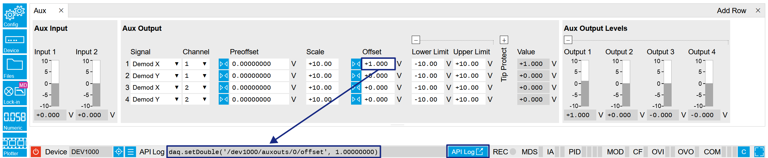
A convenient method to learn which node is responsible for a specific instrument setting is to check the Command Log history in the bottom of the LabOne User Interface. The command in the Status Bar gets updated every time a configuration change is made. Figure 1 shows how the equivalent MATLAB command is displayed after modifying the value of the auxiliary output 1's offset. The format of the LabOne UI's command history can be configured in the Config Tab (MATLAB, Python and .NET are available). The entire history generated in the current UI session can be viewed by clicking the "Show Log" button.

Figure 1: When a device's configuration is modified in the LabOne User Interface, the Status Bar displays the equivalent command to perform the same configuration via a LabOne programming interface. Here, the MATLAB code to modify auxiliary output 1's offset value is provided. When "Show Log" is clicked the entire configuration history is displayed in a new browser tab.

In a LabOne Programming Interface

A list of nodes (under a specific branch) can be requested from the Data Server in an API client using the listNodes command (MATLAB, Python, .NET) or ziAPIListNodes() function (C API). Please see each API's command reference for more help using the listNodes command. To obtain a list of all the nodes that provide data from an instrument at a high rate, so-called streaming nodes, the streamingonly flag can be provided to listNodes. More information on data streaming and streaming nodes is available in the LabOne Programming Manual.

The detailed descriptions of nodes that is provided in Reference Node Documentation is accessible directly in the LabOne MATLAB or Python programming interfaces using the "help" command. The help command is daq.help(path) in Python and ziDAQ('help', path) in MATLAB. The command returns a description of the instrument node including access properties, data type, units and available options. The "help" command also handles wildcards to return a detailed description of all nodes matching the path. An example is provided below.

    daq = zhinst.core.ziDAQServer('localhost', 8004, 6)
    daq.help('/dev1000/auxouts/0/offset')
    # Out:
    # /dev1000/auxouts/0/OFFSET#
    # Add the specified offset voltage to the signal after scaling. Auxiliary Output
    # Value = (Signal+Preoffset)*Scale + Offset
    # Properties: Read, Write, Setting
    # Type: Double
    # Unit: V

Data Server Nodes

The Data Server has nodes in the node tree available under the top-level /zi/ branch. These nodes give information about the version and state of the Data Server the client is connected to. For example, the nodes:

  • /zi/about/version
  • /zi/about/revision

are read-only nodes that contain information about the release version and revision of the Data Server. The nodes under the /zi/devices/ list which devices are connected, discoverable and visible to the Data Server.

The nodes:

  • /zi/config/open
  • /zi/config/port

are settings nodes that can be used to configure which port the Data Server listens to for incoming client connections and whether it may accept connections from clients on hosts other than the localhost.

Nodes that are of particular use to programmers are:

  • /zi/debug/logpath - the location of the Data Server's log in the PC's file system,
  • /zi/debug/level - the current log-level of the Data Server (configurable; has the Write attribute),
  • /zi/debug/log - the last Data Server log entries as a string array.

The Global nodes of the LabOne Data Server are listed in the Instrument Communication chapter of the LabOne Programming Manual

Reference Node Documentation

This section describes all the nodes in the data server’s node tree organized by branch.

AWGS

/dev..../awgs/n/auxtriggers/n/channel

Properties: Read, Write, Setting
Type: Integer (enumerated)
Unit: None

Selects the digital trigger source signal.

0 "trigin0", "trigger_input0": Trigger In 1
1 "trigin1", "trigger_input1": Trigger In 2
2 "trigin2", "trigger_input2": Trigger In 3
3 "trigin3", "trigger_input3": Trigger In 4
4 "trigout0", "trigger_output0": Trigger Out 1
5 "trigout1", "trigger_output1": Trigger Out 2
6 "trigout2", "trigger_output2": Trigger Out 3
7 "trigout3", "trigger_output3": Trigger Out 4
/dev..../awgs/n/auxtriggers/n/slope

Properties: Read, Write, Setting
Type: Integer (enumerated)
Unit: None

Select the signal edge that should activate the trigger. The trigger will be level sensitive when the Level option is selected.

0 "level_sensitive": Level sensitive trigger
1 "rising_edge": Rising edge trigger
2 "falling_edge": Falling edge trigger
3 "both_edges": Rising or falling edge trigger
/dev..../awgs/n/auxtriggers/n/state

Properties: Read
Type: Integer (64 bit)
Unit: None

State of the Auxiliary Trigger: No trigger detected/trigger detected.

/dev..../awgs/n/commandtable/clear

Properties: Read, Write, Setting
Type: Integer (64 bit)
Unit: None

Writing to this node clears all data previously loaded to the command table of the device.

/dev..../awgs/n/commandtable/data

Properties: Read, Write
Type: ZIVectorData
Unit: None

Data contained in the command table in JSON format.

/dev..../awgs/n/commandtable/schema

Properties: Read
Type: ZIVectorData
Unit: None

JSON schema describing the command table JSON format (read-only).

/dev..../awgs/n/commandtable/status

Properties: Read
Type: Integer (64 bit)
Unit: None

Status of the command table on the instrument. Bit 0: data uploaded to the command table; Bit 1, Bit 2: reserved; Bit 3: uploading of data to the command table failed due to a JSON parsing error.

/dev..../awgs/n/dio/data

Properties: Read
Type: ZIVectorData
Unit: None

A vector of 32-bit integers representing the values on the DIO interface.

/dev..../awgs/n/dio/delay/index

Properties: Read, Write, Setting
Type: Integer (64 bit)
Unit: None

Index of the bit on the DIO interface for which the delay should be changed.

/dev..../awgs/n/dio/delay/value

Properties: Read, Write, Setting
Type: Integer (64 bit)
Unit: None

Corresponding delay value to apply to the given bit of the DIO interface in units of 150 MHz clock cycles. Valid values are 0 to 3.

/dev..../awgs/n/dio/error/timing

Properties: Read, Write, Setting
Type: Integer (64 bit)
Unit: None

A 32-bit value indicating which bits on the DIO interface may have timing errors. A timing error is defined as an event where either the VALID or any of the data bits on the DIO interface change value at the same time as the STROBE bit.

/dev..../awgs/n/dio/error/width

Properties: Read, Write, Setting
Type: Integer (64 bit)
Unit: None

Indicates a width (i.e. jitter) error on either the STROBE (bit 0 of the value) or VALID bit (bit 1 of the result). A width error indicates that there was jitter detected on the given bit, meaning that an active period was either shorter or longer than the configured expected width.

/dev..../awgs/n/dio/highbits

Properties: Read, Write, Setting
Type: Integer (64 bit)
Unit: None

32-bit value indicating which bits on the 32-bit interface are detected as having a logic high value.

/dev..../awgs/n/dio/lowbits

Properties: Read, Write, Setting
Type: Integer (64 bit)
Unit: None

32-bit value indicating which bits on the 32-bit interface are detected as having a logic low value.

/dev..../awgs/n/dio/mask/shift

Properties: Read, Write, Setting
Type: Integer (64 bit)
Unit: None

Defines the amount of bit shifting to apply for the DIO wave selection in connection with playWaveDIO().

/dev..../awgs/n/dio/mask/value

Properties: Read, Write, Setting
Type: Integer (64 bit)
Unit: None

Selects the DIO bits to be used for waveform selection in connection with playWaveDIO().

/dev..../awgs/n/dio/state

Properties: Read, Write, Setting
Type: Integer (64 bit)
Unit: None

When asserted, indicates that triggers are generated from the DIO interface to the AWG.

/dev..../awgs/n/dio/strobe/index

Properties: Read, Write, Setting
Type: Integer (64 bit)
Unit: None

Select the DIO bit to use as the STROBE signal.

/dev..../awgs/n/dio/strobe/slope

Properties: Read, Write, Setting
Type: Integer (enumerated)
Unit: None

Select the signal edge of the STROBE signal for use in timing alignment.

0 "off": Off
1 "rising_edge": Rising edge trigger
2 "falling_edge": Falling edge trigger
3 "both_edges": Rising or falling edge trigger
/dev..../awgs/n/dio/strobe/width

Properties: Read, Write, Setting
Type: Integer (64 bit)
Unit: None

Specifies the expected width of active pulses on the STROBE bit.

/dev..../awgs/n/dio/valid/index

Properties: Read, Write, Setting
Type: Integer (64 bit)
Unit: None

Select the DIO bit to use as the VALID signal to indicate a valid input is available.

/dev..../awgs/n/dio/valid/polarity

Properties: Read, Write, Setting
Type: Integer (enumerated)
Unit: None

Polarity of the VALID bit that indicates that a valid input is available.

0 "none": None: VALID bit is ignored.
1 "low": Low: VALID bit must be logical zero.
2 "high": High: VALID bit must be logical high.
3 "both": Both: VALID bit may be logical high or zero.
/dev..../awgs/n/dio/valid/width

Properties: Read, Write, Setting
Type: Integer (64 bit)
Unit: None

Expected width of an active pulse on the VALID bit.

/dev..../awgs/n/elf/checksum

Properties: Read
Type: Integer (64 bit)
Unit: None

Checksum of the uploaded ELF file.

/dev..../awgs/n/elf/data

Properties: Write
Type: ZIVectorData
Unit: None

Accepts the data of the sequencer ELF file.

/dev..../awgs/n/elf/length

Properties: Read
Type: Integer (64 bit)
Unit: None

Length of the compiled ELF file.

/dev..../awgs/n/elf/memoryusage

Properties: Read
Type: Double
Unit: None

Size of the uploaded ELF file relative to the size of the main memory.

/dev..../awgs/n/elf/name

Properties: Read
Type: ZIVectorData
Unit: None

The name of the uploaded ELF file.

/dev..../awgs/n/elf/progress

Properties: Read
Type: Double
Unit: %

The percentage of the sequencer program already uploaded to the device.

/dev..../awgs/n/enable

Properties: Read, Write, Setting
Type: Integer (64 bit)
Unit: None

Activates the AWG.

/dev..../awgs/n/outputs/n/amplitude

Properties: Read, Write, Setting
Type: Double
Unit: None

Deprecated, use /DEV.../AWGS/n/OUTPUTS/m/GAINS/m instead.

/dev..../awgs/n/outputs/n/enables/n

Properties: Read
Type: Integer (64 bit)
Unit: None

Indicates the routing of the AWG signal (k index) to the wave output or to the digital mixer input (m index).

/dev..../awgs/n/outputs/n/gains/n

Properties: Read, Write, Setting
Type: Double
Unit: None

Gain factor applied to the AWG Output at the given output multiplier stage. The final signal amplitude is proportional to the Range voltage setting of the Wave signal outputs.

/dev..../awgs/n/outputs/n/hold

Properties: Read, Write, Setting
Type: Integer (64 bit)
Unit: None

Keep the last sample (constant) on the output even after the waveform program finishes.

/dev..../awgs/n/outputs/n/modulation/carriers/n/freq

Properties: Read
Type: Double
Unit: Hz

Indicates the frequency used for this carrier. The frequency is calculated with oscillator frequency times the harmonic factor.

/dev..../awgs/n/outputs/n/modulation/carriers/n/harmonic

Properties: Read, Write, Setting
Type: Integer (64 bit)
Unit: None

Multiplies the carriers's reference frequency with the integer factor defined by this field.

/dev..../awgs/n/outputs/n/modulation/carriers/n/oscselect

Properties: Read, Write, Setting
Type: Integer (64 bit)
Unit: None

Select oscillator for generation of this carrier.

/dev..../awgs/n/outputs/n/modulation/carriers/n/phaseshift

Properties: Read, Write, Setting
Type: Double
Unit: deg

Phase shift applied to carrier signal.

/dev..../awgs/n/outputs/n/modulation/mode

Properties: Read, Write, Setting
Type: Integer (enumerated)
Unit: None

Select modulation mode between off, sine modulation and advanced.

0 "off": Modulation Off: AWG Output goes directly to Signal Output.
1 "sine00": Sine 11: AWG Outputs 0 and 1 are both multiplied with Sine Generator signal 0.
2 "sine11": Sine 22: AWG Outputs 0 and 1 are both multiplied with Sine Generator signal 1.
3 "sine01": Sine 12: AWG Outputs 0 and 1 are multiplied with Sine Generator signal 0 and 1, respectively.
4 "sine10": Sine 21: AWG Outputs 0 and 1 are multiplied with Sine Generator signal 1 and 0, respectively.
5 "advanced": Advanced: Output modulates corresponding sines from modulation carriers.
6 "mixer": Mixer Calibration: The AWG outputs are multiplied with the sum or difference of Sine Generators multiplied by gains specified. The resulting output signal is AWG1(Sine1Gain1 - Sine2Gain2) + AWG2(Sine1Gain2 + Sine2Gain1).
/dev..../awgs/n/pipeliner/availableslots

Properties: Read
Type: Integer (64 bit)
Unit: None

Number of free slots in the sequence pipeliner queue. Sequence upload is blocked if this node is 0.

/dev..../awgs/n/pipeliner/commit

Properties: Read, Write
Type: Integer (64 bit)
Unit: None

Commit node data in staging area to queue of sequence pipeliner.

/dev..../awgs/n/pipeliner/enable

Properties: Read, Write, Setting
Type: Integer (64 bit)
Unit: None

Enable execution of sequences in pipeline.

/dev..../awgs/n/pipeliner/idcurrent

Properties: Read
Type: Integer (64 bit)
Unit: None

ID of sequence in staging area.

/dev..../awgs/n/pipeliner/idrunning

Properties: Read
Type: Integer (64 bit)
Unit: None

ID of executed sequence.

/dev..../awgs/n/pipeliner/maxslots

Properties: Read
Type: Integer (64 bit)
Unit: None

Maximum number of available slots in the sequence pipeliner queue.

/dev..../awgs/n/pipeliner/mode

Properties: Read, Write, Setting
Type: Integer (enumerated)
Unit: None

Selects the sequence pipeliner mode: off (default), batch, or queue mode. Changing the mode will reset both the sequence pipeliner and the normal AWG.

0 "off": Off: The sequence pipeliner is turned off.
1 "batch": Batch: The sequence pipeliner operates in batch mode. All sequences must be committed before the pipeliner is enabled. A batch can be executed once or multiple times.
2 "queue": Queue: The sequence pipeliner operates in queue mode. Sequences can be committed while the pipeliner is enabled. Every sequence is executed only once and the slot in the queue is then available for a new sequence.
/dev..../awgs/n/pipeliner/ready

Properties: Read
Type: Integer (64 bit)
Unit: None

Indicates whether a sequence can be committed to the pipeliner.

/dev..../awgs/n/pipeliner/repetitions/remaining

Properties: Read
Type: Integer (64 bit)
Unit: None

Number of remaining batch repetitions. This node is fixed to 1 if the sequence pipeliner is not in batch mode.

/dev..../awgs/n/pipeliner/repetitions/value

Properties: Read, Write, Setting
Type: Integer (64 bit)
Unit: None

Number of batch repetitions (1 to 4e6). This node is fixed to 1 if the sequence pipeliner is not in batch mode.

/dev..../awgs/n/pipeliner/reset

Properties: Read, Write
Type: Integer (64 bit)
Unit: None

Clears all sequences previously added to the sequence pipeliner and disables the pipeliner if it has been running before.

/dev..../awgs/n/pipeliner/status

Properties: Read
Type: Integer (enumerated)
Unit: None

Status of the sequence pipeliner (0: idle, 1: executing sequence, 2: waiting for next sequence to be committed (queue mode only)

0 "idle": Idle: The sequence pipeliner is idle.
1 "exec": Executing sequence: The sequence pipeliner is executing a sequence.
2 "waiting": Waiting: The sequence pipeliner is waiting for the next sequence to be committed (queue mode only).
3 "done": Done: The sequence pipeliner is still enabled but all sequences have been executed (batch mode only).
/dev..../awgs/n/pipeliner/timeout

Properties: Read, Write, Setting
Type: Integer (64 bit)
Unit: None

Maximal execution time per sequence in milliseconds. The execution of a sequence is aborted if the maximal execution time is reached. A value of 0 means infinity.

/dev..../awgs/n/ready

Properties: Read
Type: Integer (64 bit)
Unit: None

AWG has a compiled wave form and is ready to be enabled.

/dev..../awgs/n/reset

Properties: Read, Write, Setting
Type: Integer (64 bit)
Unit: None

Clears the configured AWG program and resets the state to not ready.

/dev..../awgs/n/rtlogger/clear

Properties: Read, Write, Setting
Type: Integer (64 bit)
Unit: None

Clears the logger data.

/dev..../awgs/n/rtlogger/data

Properties: Read
Type: ZIVectorData
Unit: None

Vector node with the logged events.

/dev..../awgs/n/rtlogger/enable

Properties: Read, Write, Setting
Type: Integer (64 bit)
Unit: None

Activates the Real-time Logger.

/dev..../awgs/n/rtlogger/mode

Properties: Read, Write, Setting
Type: Integer (enumerated)
Unit: None

Selects the operation mode.

0 "normal": Normal: Logger starts with the AWG and overwrites old values as soon as the memory limit of 1024 entries is reached.
1 "timestamp": Timestamp-triggered: Logger starts with the AWG, waits for the first valid trigger, and only starts recording data after the time specified by the starttimestamp. Recording stops as soon as the memory limit of 1024 entries is reached.
/dev..../awgs/n/rtlogger/starttimestamp

Properties: Read, Write, Setting
Type: Integer (64 bit)
Unit: None

Timestamp at which to start logging for timestamp-triggered mode.

/dev..../awgs/n/rtlogger/status

Properties: Read
Type: Integer (enumerated)
Unit: None

Operation state.

0 "idle": Idle: Logger is not running.
1 "normal": Normal: Logger is running in normal mode.
2 "ts_wait": Wait for timestamp: Logger is in timestamp-triggered mode and waits for start timestamp.
3 "ts_active": Active: Logger is in timestamp-triggered mode and logging.
4 "ts_full": Log Full: Logger is in timestamp-triggered mode and has stopped logging because log is full.
/dev..../awgs/n/rtlogger/timebase

Properties: Read
Type: Double
Unit: s

Minimal time difference between two timestamps. The value matches the AWG sequencer execution rate.

/dev..../awgs/n/sequencer/assembly

Properties: Read
Type: ZIVectorData
Unit: None

Displays the current sequence program in compiled form. Every line corresponds to one hardware instruction.

/dev..../awgs/n/sequencer/continue

Properties: Read, Write
Type: Integer (64 bit)
Unit: None

Reserved for future use.

/dev..../awgs/n/sequencer/memoryusage

Properties: Read
Type: Double
Unit: None

Size of the current Sequencer program relative to the available instruction memory of 16 kInstructions (16'384 instructions).

/dev..../awgs/n/sequencer/next

Properties: Read, Write
Type: Integer (64 bit)
Unit: None

Reserved for future use.

/dev..../awgs/n/sequencer/pc

Properties: Read
Type: Integer (64 bit)
Unit: None

Current position in the list of sequence instructions during execution.

/dev..../awgs/n/sequencer/program

Properties: Read
Type: ZIVectorData
Unit: None

Displays the source code of the current sequence program.

/dev..../awgs/n/sequencer/status

Properties: Read
Type: Integer (64 bit)
Unit: None

Status of the sequencer on the instrument. Bit 0: sequencer is running; Bit 1: reserved; Bit 2: sequencer is waiting for a trigger to arrive; Bit 3: AWG has detected an error; Bit 4: sequencer is waiting for synchronization with other channels.

/dev..../awgs/n/sequencer/triggered

Properties: Read
Type: Integer (64 bit)
Unit: None

When 1, indicates that the AWG Sequencer has been triggered.

/dev..../awgs/n/single

Properties: Read, Write, Setting
Type: Integer (64 bit)
Unit: None

Puts the AWG into single shot mode.

/dev..../awgs/n/sweep/awgtrigs/n

Properties: Read, Write
Type: Double
Unit: Dependent

Node used by the sweeper module for fast index sweeps. When selected as sweep grid the sweeper module will switch into a fast index based scan mode. This mode can be up to 1000 times faster than conventional node sweeps. The sequencer program must support this functionality. See section 'AWG Index Sweep' of the UHF user manual for more information.

/dev..../awgs/n/synchronization/enable

Properties: Read, Write, Setting
Type: Integer (64 bit)
Unit: None

Enable multi-channel synchronization for this AWG. The program will only execute once all channels with enabled synchronization are ready.

/dev..../awgs/n/time

Properties: Read, Write, Setting
Type: Integer (enumerated)
Unit: None

AWG sampling rate. The numeric values here are an example when the base sample rate is the default value of 2.4 GHz and are rounded for display purposes. The exact values are equal to the base sampling rate divided by 2^n, where n is the node value. The base sample clock is the node /DEV.../SYSTEM/CLOCKS/SAMPLECLOCK/FREQ. This value is used by default and can be overridden in the Sequence program.

0 2.4 GHz
1 1.2 GHz
2 600 MHz
3 300 MHz
4 150 MHz
5 75 MHz
6 37.50 MHz
7 18.75 MHz
8 9.38 MHz
9 4.69 MHz
10 2.34 MHz
11 1.17 MHz
12 585.94 kHz
13 292.97 kHz
/dev..../awgs/n/userregs/n

Properties: Read, Write, Setting
Type: Integer (64 bit)
Unit: None

Integer user register value. The sequencer has reading and writing access to the user register values during run time.

/dev..../awgs/n/waveform/descriptors

Properties: Read
Type: ZIVectorData
Unit: None

JSON-formatted string containing a dictionary of various properties of the current waveform: name, filename, function, channels, marker bits, length, timestamp.

/dev..../awgs/n/waveform/memoryusage

Properties: Read
Type: Double
Unit: %

Amount of the used waveform data relative to the device cache memory. The cache memory provides space for 256 kSa (262'144 Sa) per-channel of waveform data. Memory Usage over 100% means that waveforms must be loaded from the main memory of 64 or 512 MSa (67'108'864 Sa or 536'870'912 Sa) per-channel during playback.

/dev..../awgs/n/waveform/playing

Properties: Read
Type: Integer (64 bit)
Unit: None

When 1, indicates if a waveform is being played currently.

/dev..../awgs/n/waveform/waves/n

Properties: Read, Write
Type: ZIVectorData
Unit: None

The waveform data in the instrument's native format for the given playWave waveform index. This node will not work with subscribe as it does not push updates. For short vectors get may be used. For long vectors (causing get to time out) getAsEvent and poll can be used. The index of the waveform to be replaced can be determined using the Waveform sub-tab in the AWG tab of the LabOne User Interface.

/dev..../awgs/n/zsync/decoder/mask

Properties: Read, Write, Setting
Type: Integer (64 bit)
Unit: None

8-bit value to select the bits of the message received on ZSync interface coming from the PQSC error decoder.

/dev..../awgs/n/zsync/decoder/offset

Properties: Read, Write, Setting
Type: Integer (64 bit)
Unit: None

The additive offset applied to the message received on ZSync interface coming from the PQSC error decoder.

/dev..../awgs/n/zsync/decoder/shift

Properties: Read, Write, Setting
Type: Integer (64 bit)
Unit: None

The bit shift applied to the message received on ZSync interface coming from the PQSC error decoder.

/dev..../awgs/n/zsync/register/mask

Properties: Read, Write, Setting
Type: Integer (64 bit)
Unit: None

4-bit value to select the bits of the message received on ZSync interface coming from the PQSC readout registers.

/dev..../awgs/n/zsync/register/offset

Properties: Read, Write, Setting
Type: Integer (64 bit)
Unit: None

The additive offset applied to the message received on ZSync interface coming from the PQSC readout registers.

/dev..../awgs/n/zsync/register/shift

Properties: Read, Write, Setting
Type: Integer (64 bit)
Unit: None

The bit shift applied to the message received on ZSync interface coming from the PQSC readout registers.

CLOCKBASE

/dev..../clockbase

Properties: Read
Type: Double
Unit: Hz

Returns the internal clock frequency of the device.

CNTS

/dev..../cnts/n/enable

Properties: Read, Write, Setting
Type: Integer (64 bit)
Unit: None

Enable the pulse counter unit.

/dev..../cnts/n/gateselect

Properties: Read, Write, Setting
Type: Integer (enumerated)
Unit: None

Select the signal source used for enabling the counter in the Gated Free Running and Gated modes.

0 "trigin0", "trigger_input0": Trigger/Ref Input 1 (front panel).
1 "trigin1", "trigger_input1": Trigger/Ref Input 2 (front panel).
2 "trigin2", "trigger_input2": Trigger Input 3 (rear panel).
3 "trigin3", "trigger_input3": Trigger Input 4 (rear panel).
4 "awg_trigger0": AWG Trigger 1.
5 "awg_trigger1": AWG Trigger 2.
6 "awg_trigger2": AWG Trigger 3.
7 "awg_trigger3": AWG Trigger 4.
/dev..../cnts/n/inputselect

Properties: Read, Write, Setting
Type: Integer (enumerated)
Unit: None

Select the counter signal source.

0 DIO Bit 0.
1 DIO Bit 1.
2 DIO Bit 2.
3 DIO Bit 3.
4 DIO Bit 4.
5 DIO Bit 5.
6 DIO Bit 6.
7 DIO Bit 7.
8 DIO Bit 8.
9 DIO Bit 9.
10 DIO Bit 10.
11 DIO Bit 11.
12 DIO Bit 12.
13 DIO Bit 13.
14 DIO Bit 14.
15 DIO Bit 15.
16 DIO Bit 16.
17 DIO Bit 17.
18 DIO Bit 18.
19 DIO Bit 19.
20 DIO Bit 20.
21 DIO Bit 21.
22 DIO Bit 22.
23 DIO Bit 23.
24 DIO Bit 24.
25 DIO Bit 25.
26 DIO Bit 26.
27 DIO Bit 27.
28 DIO Bit 28.
29 DIO Bit 29.
30 DIO Bit 30.
31 DIO Bit 31.
32 "trigin0", "trigger_input0": Trigger/Ref Input 1 (front panel).
33 "trigin1", "trigger_input1": Trigger/Ref Input 2 (front panel).
34 "trigin2", "trigger_input2": Trigger Input 3 (rear panel).
35 "trigin3", "trigger_input3": Trigger Input 4 (rear panel).
/dev..../cnts/n/integrate

Properties: Read, Write, Setting
Type: Integer (64 bit)
Unit: None

Sum up counter values over time.

/dev..../cnts/n/mode

Properties: Read, Write, Setting
Type: Integer (enumerated)
Unit: None

Select the run mode of the counter unit.

1 "free_running": Free Running: The counter runs on a repetitive time base defined by the Period field. At the beginning of each period the counter is reset, and at the end, the accumulated number of counts is output.
2 "gated_free_running": Gated Free Running: The counter runs on a repetitive time base defined by the Period field. The Gate Input signal controls when the unit counter is allowed to run. The counter as well as the timer is reset when the Gate Input signal is low. The counter will only deliver new values if the Gate Input signal is high for a time longer than the configured Period.
3 "gated": Gated: The counter is controlled with the Gate Input signal. The counter is enabled at the rising edge of the Gate Input signal and disabled at the falling edge. Pulses are counted as long as the counter is enabled. The accumulated number of counts is output on the falling edge of the Gate Input signal.
4 "time_tagging": Time Tagging: Every pulse is detected individually and tagged with the time of the event. The Period defines the minimum hold-off time between the tagging of two subsequent pulses. If more than one pulse occurs within the window defined by the Period, then the pulses are accumulated and output at the end of the window. The Period effectively determines the maximum rate at which pulse information can be transmitted to the host PC.
/dev..../cnts/n/operation

Properties: Read, Write, Setting
Type: Integer (enumerated)
Unit: None

Select the arithmetic operation (addition, subtraction) applied to the counter unit outputs. 'Other counter' refers to the grouping of the counter units: 1 with 2, and 3 with 4.

0 "none": None
1 "add_other_counter": Add Other Counter
2 "subtract_other_counter": Subtract Other Counter
/dev..../cnts/n/period

Properties: Read, Write, Setting
Type: Double
Unit: s

Set the period used for the Free Running and Gated Free Running modes. Also sets the hold-off time for the Time Tagging mode.

/dev..../cnts/n/sample

Properties: Read, Stream
Type: ZICntSample
Unit: None

Streaming node containing counter values.

/dev..../cnts/n/trigfalling

Properties: Read, Write, Setting
Type: Integer (64 bit)
Unit: None

Performs a trigger event when the source signal crosses the trigger level from high to low. For dual edge triggering, select also the rising edge.

/dev..../cnts/n/trigrising

Properties: Read, Write, Setting
Type: Integer (64 bit)
Unit: None

Performs a trigger event when the source signal crosses the trigger level from low to high. For dual edge triggering, select also the falling edge.

/dev..../cnts/n/value

Properties: Read
Type: Integer (64 bit)
Unit: None

Counter output value.

DIOS

/dev..../dios/n/drive

Properties: Read, Write, Setting
Type: Integer (64 bit)
Unit: None

When on (1), the corresponding 8-bit bus is in output mode. When off (0), it is in input mode. Bit 0 corresponds to the least significant byte. For example, the value 1 drives the least significant byte, the value 8 drives the most significant byte.

/dev..../dios/n/input

Properties: Read
Type: Integer (64 bit)
Unit: None

Gives the value of the DIO input for those bytes where drive is disabled.

/dev..../dios/n/interface

Properties: Read, Write, Setting
Type: Integer (64 bit)
Unit: None

Selects the interface standard to use on the 32-bit DIO interface. A value of 0 means that a 3.3 V CMOS interface is used. A value of 1 means that an LVDS compatible interface is used.

/dev..../dios/n/mode

Properties: Read, Write, Setting
Type: Integer (enumerated)
Unit: None

Select DIO mode

0 "manual": Enables manual control of the DIO output bits.
1 "awg_sequencer_commands": Enables setting the DIO output values by AWG sequencer commands and forwards DIO input values to the AWG sequencer. The DIO interface operates at a clock frequency of 150 MHz.
2 "dio_codeword": Enables setting the DIO output values by AWG sequencer commands and forwards DIO input values to the AWG sequencer. This mode is equivalent to the mode AWG Sequencer, except for the DIO interface clock frequency which is set to 50 MHz.
3 "qccs": Enables setting the DIO output values by the ZSync input values. Forwards the ZSync input values to the AWG sequencer. Forwards the DIO input values to the ZSync output. Select this mode when the instrument is connected via ZSync to a PQSC.
/dev..../dios/n/output

Properties: Read, Write, Setting
Type: Integer (64 bit)
Unit: None

Sets the value of the DIO output for those bytes where 'drive' is enabled.

FEATURES

/dev..../features/code

Properties: Write
Type: String
Unit: None

Node providing a mechanism to write feature codes.

/dev..../features/devtype

Properties: Read
Type: String
Unit: None

Returns the device type.

/dev..../features/options

Properties: Read
Type: String
Unit: None

Returns enabled options.

/dev..../features/serial

Properties: Read
Type: String
Unit: None

Device serial number.

OSCS

/dev..../oscs/n/freq

Properties: Read, Write, Setting
Type: Double
Unit: Hz

Frequency control for each oscillator.

/dev..../oscs/n/freqawg

Properties: Read
Type: Double
Unit: Hz

Frequency as set by the AWG sequencer.

SIGOUTS

/dev..../sigouts/n/busy

Properties: Read
Type: Integer (64 bit)
Unit: None

Boolean value indicating whether a blocking process is being executed on the device. For example, locking to the external reference clock.

/dev..../sigouts/n/delay

Properties: Read, Write, Setting
Type: Double
Unit: s

This value allows to delay the output of the signal in order to align waves.

/dev..../sigouts/n/direct

Properties: Read, Write, Setting
Type: Integer (enumerated)
Unit: None

Enables the direct output path. If enabled the signal will be fed directly from the DAC, reducing delay and noise. However, the range will be fixed and offset is not available any more.

0 "amplified_path": Amplified Path
1 "direct_path": Dircet Path
/dev..../sigouts/n/filter

Properties: Read, Write, Setting
Type: Integer (64 bit)
Unit: None

Enables a filter stage in the amplified path.

/dev..../sigouts/n/max

Properties: Read
Type: Double
Unit: None

Maximum value transmitted to the DAC represented as a 16-bit integer in two's complement format.

/dev..../sigouts/n/min

Properties: Read
Type: Double
Unit: None

Minimum value transmitted to the DAC represented as a 16-bit integer in two's complement format.

/dev..../sigouts/n/offset

Properties: Read, Write, Setting
Type: Double
Unit: V

Defines the DC voltage that is added to the dynamic part of the output signal.

/dev..../sigouts/n/on

Properties: Read, Write, Setting
Type: Integer (64 bit)
Unit: None

Enabling/Disabling the Signal Output. Corresponds to the blue LED indicator on the instrument front panel.

/dev..../sigouts/n/over

Properties: Read
Type: Integer (64 bit)
Unit: None

Indicates that the signal output is overloaded.

/dev..../sigouts/n/precompensation/bounces/n/amplitude

Properties: Read, Write, Setting
Type: Double
Unit: None

Sets the amplitude of the bounce correction filter relative to the signal amplitude.

/dev..../sigouts/n/precompensation/bounces/n/delay

Properties: Read, Write, Setting
Type: Double
Unit: s

Sets the delay of the bounce correction filter.

/dev..../sigouts/n/precompensation/bounces/n/enable

Properties: Read, Write, Setting
Type: Integer (64 bit)
Unit: None

Enables (1) or disables (0) the bounce correction filter.

/dev..../sigouts/n/precompensation/bounces/n/status

Properties: Read
Type: Integer (64 bit)
Unit: None

Indicates the status of the bounce correction filter: 0 = normal, 1 = overflow during the last update period (~100 ms), 2 = overflowed in the past.

/dev..../sigouts/n/precompensation/enable

Properties: Read, Write, Setting
Type: Integer (64 bit)
Unit: None

Enables (1) or disables (0) the entire precompensation filter chain.

/dev..../sigouts/n/precompensation/exponentials/n/amplitude

Properties: Read, Write, Setting
Type: Double
Unit: None

Sets the amplitude of the exponential overshoot compensation filter relative to the signal amplitude.

/dev..../sigouts/n/precompensation/exponentials/n/enable

Properties: Read, Write, Setting
Type: Integer (64 bit)
Unit: None

Enables (1) or disables (0) the exponential overshoot compensation filter.

/dev..../sigouts/n/precompensation/exponentials/n/status

Properties: Read
Type: Integer (64 bit)
Unit: None

Indicates the status of the exponential overshoot compensation filter: 0 = normal, 1 = overflow during the last update period (~100 ms), 2 = overflowed in the past.

/dev..../sigouts/n/precompensation/exponentials/n/timeconstant

Properties: Read, Write, Setting
Type: Double
Unit: s

Sets the characteristic time constant of the exponential overshoot compensation filter.

/dev..../sigouts/n/precompensation/fir/coefficients

Properties: Read, Write, Setting
Type: ZIVectorData
Unit: s

Vector containing 40 coefficients of the finite impulse response (FIR) precompensation filter. The first eight coefficients correspond directly to the first eight taps of the FIR filter, while the remaining 32 coefficients are each applied to pairs of subsequent taps. In total the FIR filter kernel therefore has a length of 8 + 2*32 = 72 taps.

/dev..../sigouts/n/precompensation/fir/enable

Properties: Read, Write, Setting
Type: Integer (64 bit)
Unit: None

Enables (1) or disables (0) the finite impulse response (FIR) precompensation filter.

/dev..../sigouts/n/precompensation/fir/status

Properties: Read, Write, Setting
Type: Integer (64 bit)
Unit: None

Indicates the status of the finite impulse response (FIR) precompensation filter: 0 = normal, 1 = overflow during the last update period (~100 ms), 2 = overflowed in the past.

/dev..../sigouts/n/precompensation/highpass/n/clearing/slope

Properties: Read, Write, Setting
Type: Integer (enumerated)
Unit: None

When to react to a clearing pulse generated after the AWG Sequencer setPrecompClear instruction.

0 "entire_clearing_pulse": During the entire clearing pulse (Level).
1 "rising_edge": At the rising edge of clearing pulse.
2 "falling_edge": At the falling edge of the clearing pulse.
3 "both_egdes": Both, at the rising and falling edge of the clearing pulse.
/dev..../sigouts/n/precompensation/highpass/n/enable

Properties: Read, Write, Setting
Type: Integer (64 bit)
Unit: None

Enables (1) or disables (0) the high-pass compensation filter.

/dev..../sigouts/n/precompensation/highpass/n/status

Properties: Read
Type: Integer (64 bit)
Unit: None

Indicates the status of the high-pass compensation filter: 0 = normal, 1 = overflow during the last update period (~100 ms), 2 = overflowed in the past.

/dev..../sigouts/n/precompensation/highpass/n/timeconstant

Properties: Read, Write, Setting
Type: Double
Unit: s

Sets the characteristic time constant of the high-pass compensation filter.

/dev..../sigouts/n/precompensation/latency

Properties: Read
Type: Double
Unit: s

The total latency introduced by the entire precompensation filter chain.

/dev..../sigouts/n/precompensation/status/reset

Properties: Read, Write
Type: Integer (64 bit)
Unit: None

Resets the status flags of all precompensation filters of this output channel.

/dev..../sigouts/n/range

Properties: Read, Write, Setting
Type: Double
Unit: None

SINES

/dev..../sines/n/amplitudes/n

Properties: Read, Write, Setting
Type: Double
Unit: None

Sets the peak amplitude that the sine signal contributes to the signal output. Note that the last index is either 0 or 1 and will map to the pair of outputs given by the first index. (e.g. sines/3/amplitudes/0 corresponds to wave output 2)

/dev..../sines/n/enables/n

Properties: Read, Write, Setting
Type: Integer (64 bit)
Unit: None

Enables the sine signal to the signal output. Note that the last index is either 0 or 1 and will map to the pair of outputs given by the first index. (e.g. sines/3/amplitudes/0 corresponds to wave output 2)

/dev..../sines/n/harmonic

Properties: Read, Write, Setting
Type: Integer (64 bit)
Unit: None

Multiplies the sine signals's reference frequency with the integer factor defined by this field.

/dev..../sines/n/oscselect

Properties: Read, Write, Setting
Type: Integer (64 bit)
Unit: None

Select oscillator for generation of this sine signal.

/dev..../sines/n/phaseshift

Properties: Read, Write, Setting
Type: Double
Unit: deg

Phase shift applied to sine signal.

STATS

/dev..../stats/physical/fpga/aux

Properties: Read
Type: Double
Unit: V

Supply voltage of the FPGA.

/dev..../stats/physical/fpga/core

Properties: Read
Type: Double
Unit: V

Core voltage of the FPGA.

/dev..../stats/physical/fpga/temp

Properties: Read
Type: Double
Unit: °C

Internal temperature of the FPGA.

/dev..../stats/physical/overtemperature

Properties: Read
Type: Integer (64 bit)
Unit: None

This flag is set to 1 if the temperature of the FPGA exceeds 85°C. It will be reset to 0 after a restart of the device.

/dev..../stats/physical/power/currents/n

Properties: Read
Type: Double
Unit: A

Currents of the main power supply.

/dev..../stats/physical/power/temperatures/n

Properties: Read
Type: Double
Unit: °C

Temperatures of the main power supply.

/dev..../stats/physical/power/voltages/n

Properties: Read
Type: Double
Unit: V

Voltages of the main power supply.

/dev..../stats/physical/slavefpgas/n/aux

Properties: Read
Type: Double
Unit: V

Supply voltage of the FPGA.

/dev..../stats/physical/slavefpgas/n/core

Properties: Read
Type: Double
Unit: V

Core voltage of the FPGA.

/dev..../stats/physical/slavefpgas/n/temp

Properties: Read
Type: Double
Unit: °C

Internal temperature of the FPGA.

/dev..../stats/physical/temperatures/n

Properties: Read
Type: Double
Unit: °C

Internal temperature measurements.

/dev..../stats/physical/voltages/n

Properties: Read
Type: Double
Unit: V

Internal voltage measurements.

STATUS

/dev..../status/adc0max

Properties: Read
Type: Integer (64 bit)
Unit: None

The maximum value on Signal Input 1 (ADC0) during 100 ms.

/dev..../status/adc0min

Properties: Read
Type: Integer (64 bit)
Unit: None

The minimum value on Signal Input 1 (ADC0) during 100 ms

/dev..../status/adc1max

Properties: Read
Type: Integer (64 bit)
Unit: None

The maximum value on Signal Input 2 (ADC1) during 100 ms.

/dev..../status/adc1min

Properties: Read
Type: Integer (64 bit)
Unit: None

The minimum value on Signal Input 2 (ADC1) during 100 ms

/dev..../status/flags/binary

Properties: Read
Type: Integer (64 bit)
Unit: None

A set of binary flags giving an indication of the state of various parts of the device. Bit 11: Sample Loss.

/dev..../status/time

Properties: Read
Type: Integer (64 bit)
Unit: None

The current timestamp.

SYSTEM

/dev..../system/activeinterface

Properties: Read
Type: String
Unit: None

Currently active interface of the device.

/dev..../system/awg/channelgrouping

Properties: Read, Write, Setting
Type: Integer (enumerated)
Unit: None

Sets the channel grouping mode of the device.

0 "groups_of_2": Use the outputs in groups of 2. One sequencer program controls 2 outputs (use /dev..../awgs/0..4/).
1 "groups_of_4": Use the outputs in groups of 4. One sequencer program controls 4 outputs (use /dev..../awgs/0/ and /dev..../awgs/2/)
2 "groups_of_8": Use the outputs in groups of 8. One sequencer program controls 8 outputs (use /dev..../awgs/0/). Requires 8 channel device.
/dev..../system/awg/oscillatorcontrol

Properties: Read, Write, Setting
Type: Integer (enumerated)
Unit: None

Sets the oscillator control mode.

0 "api": Oscillators are controlled by the UI/API.
1 "awg_sequencer": Oscillators are controlled by the AWG sequencer.
/dev..../system/boardrevisions/n

Properties: Read
Type: String
Unit: None

Hardware revision of the FPGA base board

/dev..../system/clocks/referenceclock/freq

Properties: Read
Type: Double
Unit: Hz

Indicates the frequency of the reference clock.

/dev..../system/clocks/referenceclock/source

Properties: Read, Write, Setting
Type: Integer (enumerated)
Unit: None

Reference clock source.

0 "internal": The internal clock is used as the frequency and time base reference.
1 "external": An external clock is intended to be used as the frequency and time base reference. Provide a clean and stable 10MHz or 100MHz reference to the appropriate back panel connector.
2 "zsync": A ZSync clock is intended to be used as the frequency and time base reference.
/dev..../system/clocks/referenceclock/status

Properties: Read
Type: Integer (enumerated)
Unit: None

Status of the reference clock.

0 "locked": Reference clock has been locked on.
1 "error": There was an error locking onto the reference clock signal. After an error the source is automatically switched back to internal reference clock.
2 "busy": The device is busy trying to lock onto the reference clock signal.
/dev..../system/clocks/sampleclock/freq

Properties: Read, Write, Setting
Type: Double
Unit: Hz

Indicates the frequency of the sample clock. Changing the sample clock temporarily interrupts the AWG sequencers.

/dev..../system/clocks/sampleclock/outputenable

Properties: Read, Write, Setting
Type: Integer (enumerated)
Unit: None

Enable the sampleclock output.

0 "on": Sample clock output is disabled.
1 "off": Sample clock output is enabled.
/dev..../system/clocks/sampleclock/status

Properties: Read
Type: Integer (enumerated)
Unit: None

Status of the sample clock.

0 "locked": Sample clock signal is valid and has been locked on.
1 "error": There was an error adjusting the sample clock.
2 "busy": The device is busy trying to adjust the sample clock.
/dev..../system/fpgarevision

Properties: Read
Type: Integer (64 bit)
Unit: None

HDL firmware revision.

/dev..../system/fwlog

Properties: Read
Type: String
Unit: None

Returns log output of the firmware.

/dev..../system/fwlogenable

Properties: Read, Write
Type: Integer (64 bit)
Unit: None

Enables logging to the fwlog node.

/dev..../system/fwrevision

Properties: Read
Type: Integer (64 bit)
Unit: None

Revision of the device-internal controller software.

/dev..../system/fx3revision

Properties: Read
Type: String
Unit: None

USB firmware revision.

/dev..../system/identify

Properties: Read, Write
Type: Integer (64 bit)
Unit: None

Setting this node to 1 will cause the device to blink the power led for a few seconds.

/dev..../system/kerneltype

Properties: Read
Type: String
Unit: None

Returns the type of the data server kernel (mdk or hpk).

/dev..../system/nics/n/defaultgateway

Properties: Read, Write
Type: String
Unit: None

Default gateway configuration for the network connection.

/dev..../system/nics/n/defaultip4

Properties: Read, Write
Type: String
Unit: None

IPv4 address of the device to use if static IP is enabled.

/dev..../system/nics/n/defaultmask

Properties: Read, Write
Type: String
Unit: None

IPv4 mask in case of static IP.

/dev..../system/nics/n/gateway

Properties: Read
Type: String
Unit: None

Current network gateway.

/dev..../system/nics/n/ip4

Properties: Read
Type: String
Unit: None

Current IPv4 of the device.

/dev..../system/nics/n/mac

Properties: Read
Type: String
Unit: None

Current MAC address of the device network interface.

/dev..../system/nics/n/mask

Properties: Read
Type: String
Unit: None

Current network mask.

/dev..../system/nics/n/saveip

Properties: Read, Write
Type: Integer (64 bit)
Unit: None

If written, this action will program the defined static IP address to the device.

/dev..../system/nics/n/static

Properties: Read, Write
Type: Integer (64 bit)
Unit: None

Enable this flag if the device is used in a network with fixed IP assignment without a DHCP server.

/dev..../system/porttcp

Properties: Read, Write
Type: Integer (64 bit)
Unit: None

Returns the current TCP port used for communication to the dataserver.

/dev..../system/portudp

Properties: Read, Write
Type: Integer (64 bit)
Unit: None

Returns the current UDP port used for communication to the dataserver.

/dev..../system/powerconfigdate

Properties: Read
Type: Integer (64 bit)
Unit: None

Contains the date of power configuration (format is: (year << 16) | (month << 8) | day)

/dev..../system/preset/busy

Properties: Read
Type: Integer (64 bit)
Unit: None

Indicates if presets are currently loaded.

/dev..../system/preset/error

Properties: Read
Type: Integer (64 bit)
Unit: None

Indicates if the last operation was illegal. Successful: 0, Error: 1.

/dev..../system/preset/load

Properties: Read, Write
Type: Integer (64 bit)
Unit: None

Load the selected preset.

/dev..../system/properties/freqresolution

Properties: Read
Type: Integer (64 bit)
Unit: None

The number of bits used to represent a frequency.

/dev..../system/properties/maxfreq

Properties: Read
Type: Double
Unit: None

The maximum oscillator frequency that can be set.

/dev..../system/properties/minfreq

Properties: Read
Type: Double
Unit: None

The minimum oscillator frequency that can be set.

/dev..../system/properties/negativefreq

Properties: Read
Type: Integer (64 bit)
Unit: None

Indicates whether negative frequencies are supported.

/dev..../system/properties/timebase

Properties: Read
Type: Double
Unit: s

Minimal time difference between two timestamps. The value is equal to 1/(maximum sampling rate).

/dev..../system/saveports

Properties: Read, Write
Type: Integer (64 bit)
Unit: None

Flag indicating that the TCP and UDP ports should be saved.

/dev..../system/shutdown

Properties: Read, Write
Type: Integer (64 bit)
Unit: None

Sending a '1' to this node initiates a shutdown of the operating system on the device. It is recommended to trigger this shutdown before switching the device off with the hardware switch at the back side of the device.

/dev..../system/slaverevision

Properties: Read
Type: Integer (64 bit)
Unit: None

HDL firmware revision of the slave FPGA.

/dev..../system/stall

Properties: Read, Write
Type: Integer (64 bit)
Unit: None

Indicates if the network connection is stalled.

/dev..../system/synchronization/source

Properties: Read, Write, Setting
Type: Integer (enumerated)
Unit: None

Selects the source for synchronization of channels: internal (default) or external

0 "internal": Internal: Synchronization of all channels of a device that have the corresponding synchronization setting enabled.
1 "external": External: Same as internal plus synchronization to other devices via ZSync.
/dev..../system/update

Properties: Read, Write
Type: Integer (64 bit)
Unit: None

Requests update of the device firmware and bitstream from the dataserver.

TRIGGERS

/dev..../triggers/in/n/imp50

Properties: Read, Write, Setting
Type: Integer (64 bit)
Unit: None

Trigger input impedance: When on, the trigger input impedance is 50 Ohm, when off 1 k Ohm.

/dev..../triggers/in/n/level

Properties: Read, Write, Setting
Type: Double
Unit: V

Trigger voltage level at which the trigger input toggles between low and high. Use 50% amplitude for digital input and consider the trigger hysteresis.

/dev..../triggers/in/n/value

Properties: Read
Type: Integer (64 bit)
Unit: None

Shows the trigger input. The value integrated over some time. Values are 1: low, 2: high, 3: was low and high in the period.

/dev..../triggers/out/n/delay

Properties: Read, Write, Setting
Type: Double
Unit: s

Trigger delay, controls the fine delay of the trigger output. The resolution is 78 ps.

/dev..../triggers/out/n/source

Properties: Read, Write, Setting
Type: Integer (enumerated)
Unit: None

Assign a signal to a marker.

0 "awg_trigger0": Trigger output is assigned to AWG Trigger 1, controlled by AWG sequencer commands.
1 "awg_trigger1": Trigger output is assigned to AWG Trigger 2, controlled by AWG sequencer commands.
2 "awg_trigger2": Trigger output is assigned to AWG Trigger 3, controlled by AWG sequencer commands.
3 "awg_trigger3": Trigger output is assigned to AWG Trigger 4, controlled by AWG sequencer commands.
4 "output0_marker0": Output is assigned to Output 1 Marker 1.
5 "output0_marker1": Output is assigned to Output 1 Marker 2.
6 "output1_marker0": Output is assigned to Output 2 Marker 1.
7 "output1_marker1": Output is assigned to Output 2 Marker 2.
8 "trigin0", "trigger_input0": Output is assigned to Trigger Input 1.
9 "trigin1", "trigger_input1": Output is assigned to Trigger Input 2.
10 "trigin2", "trigger_input2": Output is assigned to Trigger Input 3.
11 "trigin3", "trigger_input3": Output is assigned to Trigger Input 4.
12 "trigin4", "trigger_input4": Output is assigned to Trigger Input 5.
13 "trigin5", "trigger_input5": Output is assigned to Trigger Input 6.
14 "trigin6", "trigger_input6": Output is assigned to Trigger Input 7.
15 "trigin7", "trigger_input7": Output is assigned to Trigger Input 8.
17 "high": Output is set to high.
18 "low": Output is set to low.
/dev..../triggers/streams/n/enable

Properties: Read, Write, Setting
Type: Integer (64 bit)
Unit: None

Enables trigger streaming.

/dev..../triggers/streams/n/holdofftime

Properties: Read, Write, Setting
Type: Double
Unit: s

Sets the holdoff time of the trigger unit.

/dev..../triggers/streams/n/mask

Properties: Read, Write, Setting
Type: Integer (64 bit)
Unit: None

Masks triggers for the current stream. The mask is bit encoded where bit 0..7 are the input triggers and bit 8..11 are AWG triggers.

/dev..../triggers/streams/n/sample

Properties: Read, Stream
Type: ZITrigSample
Unit: None

Streaming node containing the trigger data. Note that this will only deliver data if triggers are detected.