Pulse Counter Tab
The Pulse Counter tab relates to the HDAWG-CNT Pulse counter option and is only available if this option is installed on the instrument (see Information section in the Device tab). The number of counter modules depends on the number of channels of the instrument.
Features
- 4 or 8 counter modules
- 300 MHz maximum count rate
- 4 modes: free running, gated, gated free running, and pulse tagging
- 4 or 8 analog signal inputs with adjustable discriminator level
- 32 digital signal inputs
- Background subtraction
- Count integration
Description
The Pulse Counter tab provides access to the pulse counter settings. Whenever the tab is closed or an additional one of the same type is needed, clicking the following icon will open a new instance of the tab.
| Control/Tool | Option/Range | Description |
|---|---|---|
| Counter | Configure the Pulse Counters for analysis of pulse trains on the digital signal inputs. |
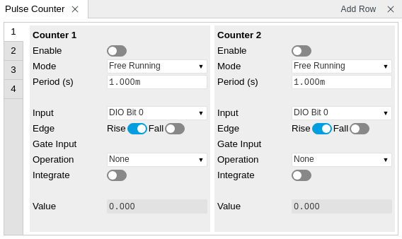
The Pulse Counter tab shown in Figure 1 consists of four side-tabs, one for each Counter module. The Enable button and the Mode selector are the main controls that determine if and how a Counter unit generates an output. The output is displayed in the Value field and is available in the Plotter and Data Acquisition tab.
The counter Input signal is selectable among the Trigger inputs as well as any of the 32 DIO channels on the VHDCI connector on the instrument rear panel. The trigger level of the analog trigger inputs is configurable in the DIO tab. The following operation modes are available.
- Free running: the counter is active during repeated periods defined by the a configurable timer. The timer period is controlled by the Period field. At the beginning of the period the counter is reset, and at the end, the accumulated number of counts is output.
- Gated: the counter is controlled with the Gate Input signal. The counter is enabled at the rising edge of the Gate Input signal and disabled at the falling edge. Pulses are counted as long as the counter is enabled. The accumulated number of counts is output on the falling edge of the Gate Input signal.
- Gated free running: the counter runs on a repetitive time base defined by the Period field. The Gate Input signal controls when the counter is allowed to run. The counter as well as the timer is reset when the Gate Input signal is low. The counter will only deliver new values if the Gate Input signal is high for a time longer than the configured Period.
- Time tagging: every single event is counted and transmitted to the server along with a time tag. The Period defines the minimum hold-off time between the tagging of two subsequent pulses. If more than one pulse occurs within the window defined by the Period, then the pulses are accumulated and output at the end of the window. The Period effectively determines the maximum rate at which pulse information can be transmitted to the host PC.
Background subtraction or summation of data from two counter modules is controlled by the Operation field. For add and subtract operations, counter units 1 is grouped with unit 2, and unit 3 is grouped with unit 4. The Pulse Counter supports integration of counter data over time. The integer timestamp in all recorded data is in units of the instrument data clock, 1.8 GHz.
Note
It is recommended to use the 1GbE interface rather than the USB interface in combination with the Pulse Counter. 1GbE provides a higher stability at high data rates, namely in time tagging mode or in free-running mode with a small Period setting.
Functional Elements
| Control/Tool | Option/Range | Description |
|---|---|---|
| Enable | ON / OFF | Enable the pulse counter unit. |
| Mode | Select the run mode of the counter unit. | |
| Free Running | The counter runs on a repetitive time base defined by the Period field. At the beginning of each period the counter is reset, and at the end, the accumulated number of counts is output. | |
| Gated Free Running | The counter runs on a repetitive time base defined by the Period field. The Gate Input signal controls when the unit counter is allowed to run. The counter as well as the timer is reset when the Gate Input signal is low. The counter will only deliver new values if the Gate Input signal is high for a time longer than the configured Period. | |
| Gated | The counter is controlled with the Gate Input signal. The counter is enabled at the rising edge of the Gate Input signal and disabled at the falling edge. Pulses are counted as long as the counter is enabled. The accumulated number of counts is output on the falling edge of the Gate Input signal. | |
| Time Tagging | Every pulse is detected individually and tagged with the time of the event. The Period defines the minimum hold-off time between the tagging of two subsequent pulses. If more than one pulse occurs within the window defined by the Period, then the pulses are accumulated and output at the end of the window. The Period effectively determines the maximum rate at which pulse information can be transmitted to the host PC. | |
| Period | 93.3 ns to 1 s | Set the period used for the Free Running and Gated Free Running modes. Also sets the hold-off time for the Time Tagging mode. |
| Input | Ref/Trigger 1-8, AWG Trigger 1-4, DIO Bit 0-31 | Select the counter signal source. |
| Edge Rise | ON / OFF | Performs a trigger event when the source signal crosses the trigger level from low to high. For dual edge triggering, select also the falling edge. |
| Edge Fall | ON / OFF | Performs a trigger event when the source signal crosses the trigger level from high to low. For dual edge triggering, select also the rising edge. |
| Gate Input | Ref/Trigger Input 1/2, Trigger Input 3/4, AWG internal Trigger 1-4 | Select the signal source used for enabling the counter in the Gated Free Running and Gated modes. |
| Operation | Subtract Other Counter | Select the arithmetic operation (addition, subtraction) applied to the counter unit outputs. "Other counter" refers to the grouping of the counter units: 1 with 2, and 3 with 4. |
| None | ||
| Add Other Counter | ||
| Integrate | ON / OFF | Sum up counter values over time. |
| Value | Displays the counter output value. |