Signal Generation and Output
The Output tab provides the electrical configuration of the Wave outputs and all configuration of the AWG and sine generator signals. It is available on all HDAWG instruments.
Features
- Sequencer run/stop control
- Sine generator configuration: frequency, harmonic, phase, amplitude
- AWG modulation control
- Output enable, range, amplification, and filter settings
Description
| Control/Tool | Option/Range | Description |
|---|---|---|
| Output | Quick overview and access to all the settings and properties for signal generation and modulation. |
The Output tab (see Figure 1) is divided into four sections: Oscillators, Sine Generators, Waveform Generators, and Wave outputs.
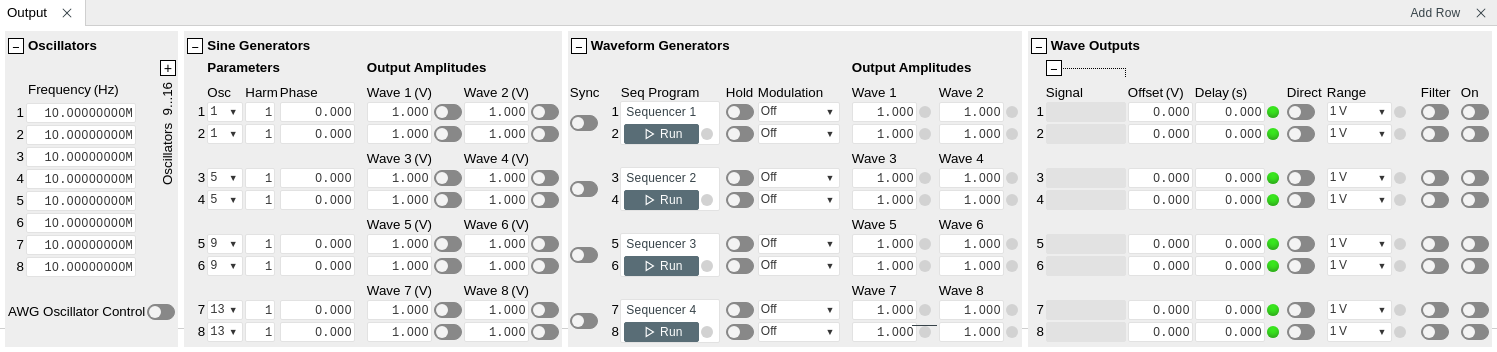
The purpose of the Output tab is to configure how the waveform signals previously prepared in the AWG Sequencer tab are routed to the Wave outputs of the instrument. The tabular layout of the tab provides a quick overview of the status of the different AWG cores on the instrument (see AWG Architecture and Execution Timing for an overview on the internal architecture and terminology), and enables quick access to all necessary settings to configure the modulation (i.e. multiplication) and addition of sinusoidal and AWG signals.
Conceptually, the tab is laid out as follows: The Wave Outputs section
represents the physical outputs of the device in horizontal rows. The
signal on a given Wave output can be a multiplication, or addition, or
both, of AWG and sine signals, depending which modulation mode is used.
The Signal field contains a representation of the current signal
generated on one output in the form of a simple formula (e.g.,
Sine 1 + AWG 1×Sine 2).
The individual Sine and AWG signals are configured respectively in the Sine Generators and Waveform Generators section. The horizontal rows in these sections represent the digital signals generated by the Sine Generators and Arbitrary Waveform Generator channels. The Output Amplitudes section represent the pair-wise matrix-like routing of these signal (rows) to the Wave outputs (columns) and the amplitude of each.
The rows in the Waveform Generator and the Sine Generators section are graphically grouped in two, and each pair is associated with a pair of Wave outputs. This arrangement reflects the AWG Architecture and Execution Timing of the instrument, where one front end FPGA per pair of Wave outputs contains one dual-channel AWG core, and one pair of sine generators.
Note
In the following paragraphs, all the descriptions are for a single AWG Core and corresponding wave out channel pair.
Signal routing control
The Signal Routing block directs the output of the two AWG channels to the modulation block via four signal switches. It's possible to direct both AWG channels to both of the modulation blocks or any subset of them and create complex modulated signals, depending on the modulation mode selected.

Signal Routing is controlled by the AWG sequencer for each waveform played. This can be done either in the playWave instruction or in the command table definition.
When playWave is used, the signal routing can be controlled with the argument before the waveform to be played.
playWave(WAVEs_OUT_CH0, WAVE_AWG_CH0, {WAVEs_OUT_CH1, WAVE_AWG_CH1});
1 and 2 before a wave indicate that the output of the relative AWG channel should be directed to the specified Wave Output modulator. In other words, to control the switches OUTi_CHj in Figure 2, the i refers to the used indices 1 or 2, while their position (before the first wave or before of the second wave) refers to the j. To direct the output of a AWG channel to both modulator the sequence 1,2 can be used. For example playWave(1, w1, 2, w2) will direct w1 to the modulator of Wave output 1 and w2 to the modulator of Wave output 1 (switches OUT1_CH0 and OUT2_CH1 closed). See more common examples in Table 2. The routing can be omitted from the playWave; in this case, it's assumed that each channel goes to its corresponding wave output. A wave can also be omitted by using two pairs of mark "" to mark the omission; this only works for the first wave in the arguments of playWave.
| playWave Arguments | Typical usage | OUT1_CH0 | OUT1_CH1 | OUT2_CH0 | OUT2_CH1 |
|---|---|---|---|---|---|
w1 |
no or amplitude modulation on wave out 1, nothing on wave out 2 | ON | OFF | OFF | OFF |
1,"", 2,w2 |
no or amplitude modulation on wave out 2, nothing on wave out 1 | OFF | OFF | OFF | ON |
"", w2 |
same as above | OFF | OFF | OFF | ON |
1,w1, 2,w2 |
no or amplitude modulation on wave out 1 and 2 | ON | OFF | OFF | ON |
w1, w2 |
Same as above | ON | OFF | OFF | ON |
1,wI, 1,wQ |
IQ modulation on wave out 1 | ON | ON | OFF | OFF |
2,wI, 2,wQ |
IQ modulation on wave out 2 | OFF | OFF | ON | ON |
1,2,wI, 1,2,wQ |
"Mixer calibration" modulation mode | ON | ON | ON | ON |
When the command table is used to play waveform, the Signal routing can be controlled in two ways:
- In the waveform definition with
assignWaveIndex. The syntax is the same asplayWave - In the command table definition, using the elements Waveform > awgChannel0/1. Please refer to the Command table fields definitions.
Modulation
The HDAWG supports many different modulation schemes. It can be selected for each wave output in the "Modulation" field or with the node /DEV.../AWGS/n/OUTPUTS/N/MODULATION/MODE. Four gain coefficients can be set from the "Output Amplitudes" fields or with the nodes /DEV.../AWGS/n/OUTPUTS/i/GAINS/j, with their meaning depending on the modulation mode.
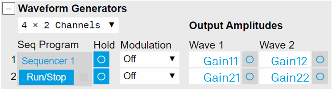
For each modulation mode, gains are used with a different meaning, explained below. The diagram in each mode is intended to be in the "Modulation" block in Figure 2.
No modulation
When the "Modulation" is set to "Off", the AWG signals are not modulated. Each signal is multiplied by the relative gain and summed. For the wave output \(k\) the output would be

Typically only the diagonal coefficients are used in this mode.
Sine modulation
When the "Modulation" is set to "Sineij", the AWG signals are modulated by the two Sine Generators. The indices determine which Sine Generator is used for the two AWG signals; Sine Generator "i" is multiplied to the AWG signal from channel 0 and Sine Generator "j" is multiplied to the AWG signal from channel 1, both with the relative gain \(G_{k0/1}\). Finally, both modulated signals are summed:
Note
The indices used in "Sineij" in the UI depends on the AWG core used. They are 1 and 2 for the first AWG core, 3 and 4 for the second and so on. However their value is identical in the node setting, see /dev.../awgs/n/outputs/n/modulation/mode

The most common use case is to perform amplitude modulation of both AWG channel signals. In this case the mode is set to "Sine11" on the first output channel and "Sine22" on the second. A single waveform is sent to each channel modulator with playWave(1,w1, 2,w2). If only one channel is used, a waveform can be omitted as shown in Table 2.
The output will be \(\text{Sine}_1 \times \text{Gain}_{00} \times \text{AWG\_CH0}\) on the first wave out and \(\text{Sine}_1 \times \text{Gain}_{00} \times \text{AWG\_CH0}\) one the second.
This modulation mode can be also used to perform IQ modulation at full sample rate on a single wave out channel; the other will be muted. Both Sine Generators are needed to generate the in-phase and the in-quadrature carrier. In order to generate such modulated pulses on wave out 1 (wave out 2) proceed as follows:
- Set the modulation mode of channels 1(2) to "Sine12".
- If the MF option is installed, connect both Sine Generators 1 and 2 to the same oscillator (e.g. oscillator 1)
- Set the phase of Sine Generator 1 to 90 degrees
- Set the phase of Sine Generator 2 to 0 degrees
- Set Gain00 and Gain01 (Gain10 and Gain11) to 0.5
- Play AWG signals using an instruction of the form
playWave(1, w_I, 1, w_Q);(playWave(2, w_I, 2, w_Q);), where the waveformsw_Iandw_Qare in-phase and quadrature components of the pulse
The output will be
or more compactly
where
In other words, if the AWG outputs (multiplied by the correct gain) form a 2-element vector, the instantaneous amplitude will be the modulus of that vector, and the instantaneous phase will be its angle.
Mixer Calibration modulation
When the "Modulation" is set to "Mixer Calib", the AWG signals are modulated by a weighted sum of the Sine Generators. The weights are given by the gains. This is to generate IQ baseband signals meant to be sent to a external IQ upconverter modulator or mixer, like the HDIQ. Since physical mixers are not ideal, this mode can be used to compensate for non-idealities of the mixer. The output on wave out k is

A perfect IQ mixer generates the following signal \(V_{\text{RF}}(t)\) at its RF port:
where \(V_{\text{I}}(t)\) and \(V_{\text{Q}}(t)\) are input signals at the mixer I and Q ports, and \(\omega_{\text{LO}}\) is the local oscillator frequency. A real mixer is characterized by a certain phase imbalance \(\theta\) and amplitude imbalance \(\alpha\), so that it effectively performs the following operation:
In order to generate a continuous signal at the lower sideband \(\omega_{\text{LO}} - \omega\) relative to the local oscillator frequency, and at the same time suppress the upper sideband \(\omega_{\text{LO}} + \omega\), the following signals need to be applied to the mixer I and Q ports:
Conversely, in order to generate a signal at the upper sideband \(\omega_{\text{LO}} + \omega\), the following signals need to be applied:
In order to generate a phase-modulated pulse (e.g., a DRAG pulse) with these imbalance parameters \(\theta\) and \(\alpha\) at the upper sideband, proceed as follows:
- Set the modulation mode of channels 1 and 2 to Mixer Calib.
- If the MF option is installed, connect Sine Generators 1 and 2 both to the same oscillator
- Set the phase of Sine Generator 1 to 90 degrees
- Set the phase of Sine Generator 2 to 0 degrees
- Determine a normalization parameter \(\lambda\)
- Set Gain00 to \(\lambda\)
- Set Gain01 to \(-\lambda \times \tan(\theta)\)
- Set Gain10 to 0
- Set Gain11 to \(\frac{-\lambda}{\alpha\cos(\theta)}\)
- Play AWG signals using an instruction of the form
playWave(1,2, wI, 1,2, wQ);, where the waveformswIandwQare in-phase and quadrature components of the pulse.
In this configuration, Sine Generator 1 will generate a signal \(\cos(\omega t)\) with the frequency \(\omega\) of the oscillator. Sine Generator 2 will generate a signal \(\sin(\omega t)\).
The normalization parameter \(\lambda < 1\) ensures that the sum remains smaller than 1 at all times. This prevents clipping caused by an overflow of the digital signal that enters the digital-to-analog converter.
We may write the operation of the output modulation stage in this configuration in matrix form:
In order to generate a signal at the lower sideband of the LO frequency, it is recommended to use the settings as above, however set the frequency of the AWG oscillator to the desired negative value.
Advanced modulation (multifrequency)
When the "Modulation" is set to "Advanced", the corresponding channel can modulate 4 sine signals that are independent in terms of frequency, phase, and envelope signal. This is realized by de-interleaving the flow of samples from one AWG output into four signals with four-fold reduced sampling rate, multiplying each of them to an individual sine signal, adding up the resulting signals, and sending that sum signal to the DAC. This can be used to realize frequency-domain multiplexing. The modulated signal is
While each AWG sub-carrier is at one-quarter of the sample rate, the sine generators work at full sample rate, so there are no limitations on the maximum frequency, but only on the bandwidth of the baseband signals.
Differently from all the other modulation modes, the signal routing is done after the modulation. In this way, it's possible to direct the output of both AWG channels to a single wave output and generate a 8 frequency modulated signal.

Gains are not used in this mode.
Note
The Sine generators used in this mode are separate from the ones used by other modulation modes, while the oscillators are the same. The sine generators can be configured in the Multi Frequency Modulation Tab
Functional Elements
| Control/Tool | Option/Range | Description |
|---|---|---|
| Frequency (Hz) | 0 to 1.2 GHz | Frequency control for each oscillator. |
| Frequency (Hz) | Oscillator frequency when AWG Oscillator Control is enabled. In this mode, the frequencies cannot be changed from the user interface, but only through an AWG sequence program. When disabling AWG Oscillator Control, the frequencies are reset to the previous setting. | |
| Oscillator Control | Sets the oscillator control mode of the device. | |
| UI/API | Oscillators are controlled by the UI/API. | |
| AWG | Oscillators are controlled by the AWG sequencer. | |
| Oscillator Selection | 1 to 16 | Selection of the oscillator used for the generated sine signal. |
| Harmonics | 1 to 1023 | Multiplies the oscillator's reference frequency with the integer factor defined by this field. |
| Phase | -180 to +180 degree | Sets the phase of the sine signal. |
| Amplitude | 0 to 5 V (depending on range) | Sets the amplitude of the sine signal. |
| Enable | ON / OFF | Enables the given sine signal (row) to the Wave output (column). The signal is added to other signals present on the given Wave output. |
| Synchronization Enable | Enable multi-channel synchronization for this AWG core. The program will only execute once all AWG cores with enabled synchronization are ready. | |
| Run | Runs the AWG Sequencer. In MDS mode, use the start button on the sequencer tab to start all Sequencers in the correct order. | |
| Hold | Keep the last sample (constant) on the output even after the waveform program finishes. It is recommended to use only AWG waveforms with lengths equal to a multiple of 16 together with this functionality. Waveforms with other lengths are automatically padded with zeros at the end by the AWG Compiler. The status of the hold node is checked only when the AWG is enabled. If hold is disabled after enabling the AWG or when the AWG is not running, AWG output values will still be held. | |
| Modulation | Sets the modulation mode of the given AWG output. The notation Sine NM with N, M = 1, 2, ... signifies the following: the given AWG output is multiplied with the signal of Sine Generator N when routed to the first Wave output of the given AWG core, and with the signal of Sine Generator M when routed to the second Wave output of the given AWG core. In Advanced mode, 4 envelope signals are generated with the given AWG output using sample interleaving. Each envelope is multiplied with one sinusoid signal generated by the MF Modulation block represented in the MF Modulation tab. In Mixer Calibration mode, the AWG outputs are multiplied with the sum or difference of Sine Generators multiplied by gains specified so that the resulting output signal is ( AWG1*(Sine1*Gain1 - Sine2*Gain2) + AWG2*(Sine1*Gain2 + Sine2*Gain1) ). | |
| Amplitude | Sets the amplitude scaling factor of the given AWG channel. The amplitude is dimensionless scaling factor applied to the digital signal. | |
| Signal path enabled | Indicates the routing of the AWG signal (row) to the Wave output or to the digital mixer input (column). | |
| Signal | string | Indicates which signals are combined to generate the output wave. |
| Offset (V) | -2.5 V to +2.5 V | Sets the analog offset voltage of the Wave output in amplified mode. The set value applies to a high-impedance load. For a 50 Ω load, the voltage at the load is half of the set value. |
| Delay | Delay the output of the signal in order to align waves. | |
| Delay Status | red/green | Indicates the status of setting the delay. Red: The delay setting is still in progress. Green: Delay has been set and output is ready. |
| Direct | ON / OFF | Enables the direct output mode in which the signal from the digital-to-analog converter is connected to the Wave connector without further amplification. This mode provides the highest bandwidth and lowest broadband noise. The range is fixed to 800 mV, and the signal contains spurs at the sampling frequency due to the absence of anti-alias filtering. |
| Range | 200 mV to 5 V | Defines the maximum output voltage that is generated by the corresponding Wave output. This includes the potential multiple AWG and Sine Amplitudes and Offsets summed up. Select the smallest range possible to optimize signal quality. |
| Filter | ON / OFF | Enables the analog output filter. |
| On | Main switch for the Wave output corresponding to the LED indicator on the instrument front panel. |