External Reference
Note
This tutorial is applicable to all MFLI Instruments. No specific options are required. The user interface has slight differences depending on whether the MF-MD Multi-demodulator option is installed or not. The tutorial provides separate instructions for both cases.
Goals and Requirements
This tutorial explains how to lock an internal oscillator to an external reference frequency, and then demodulate a measurement signal at a harmonic of this frequency. To follow this tutorial, you need an optical chopper as well as a standard optical detector/emitter pair. However, the tutorial applies to any comparable setup in which separate reference and signal channels are available. The reference channel should have a sufficiently large amplitude (e.g., TTL level) to allow for reliable locking.
Preparation
Connect the cables as shown in Figure 1. Make sure the MFLI is powered on, and then connect the MFLI through USB to your PC, or to your local area network (LAN) where the host computer resides. After connecting to your Instrument through the web browser using its address, the LabOne graphical user interface is opened. Check the Getting Started for detailed instructions. The tutorial can be started with the default instrument configuration (e.g. after a power cycle) and the default user interface settings (i.e. as is after pressing F5 in the browser).

Activate the External Reference Mode
The reference signal is wired from the sync output of the optical chopper to the Aux Input 1/Ref of the MFLI. In our case, the reference signal is a square signal switching between 0 V and 5 V. We choose a base frequency of 80 Hz on the chopper. You can inspect the signal easily by going to the Scope tab and selecting Aux In 1 Ch 1 as the input signal.
Locking the internal oscillator to the external signal looks slightly different depending on the installed options, notably if the MF-MD Multi-demodulator option is installed or not. We therefore describe the required steps separately for both cases.
Without MF-MD Multi-demodulator option: Open the graphical Lock-in tab. In the Internal/External Reference section on the bottom row of that tab, the section label is actually a control which can be toggled between Internal Reference (default) and External Reference. Set it to External Reference. To the right of that control, you can now select the input signal. Select Aux In 1 as the input signal. These settings are also shown in Figure 2. The frequency value displayed in the center of the reference section should quickly convert to the 80 Hz of the chopper. The Lock-in settings used to lock to the external reference without MF-MD Multi-demodulator option are shown in the following table.
| Tab | Section | # | Label | Setting / Value / State |
|---|---|---|---|---|
| Lock-in | Internal/External Reference | 1 | Internal/External Reference | External Reference |
| Lock-in | Internal/External Reference | 1 | Internal/External Reference | Aux In 1 |
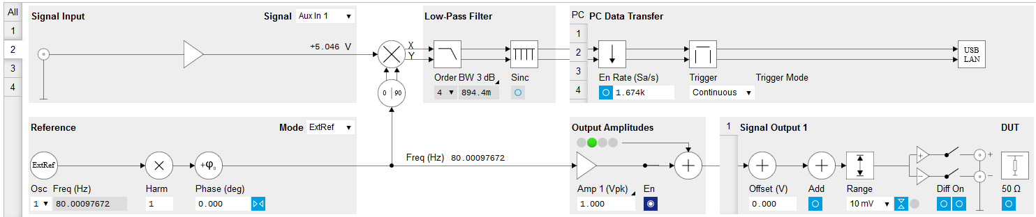
With MF-MD Multi-demodulator option: Open the graphical Lock-in tab of the second demodulator. We use this demodulator to establish the phase-locked loop (PLL) between the internal oscillator 1 and the external signal. In the Reference section at the bottom left of the Lock-in tab, select ExtRef in the Mode field and select oscillator number 1. In the Signal Input section top left, select Aux In 1 as the input signal. These settings are also shown in Figure 3. The frequency of oscillator 1 displayed in the Reference section should quickly converge to the 80 Hz of the chopper. The Lock-in settings for enabling the lock to the external reference with MF-MD Multi-demodulator option are shown in Table 2.
| Tab | Section | # | Label | Setting / Value / State |
|---|---|---|---|---|
| Lock-in | Reference | 2 | Mode | ExtRef |
| Lock-in | Reference | 2 | Osc | 1 |
| Lock-in | Signal Input | 2 | Signal | Aux In 1 |
At this point, it is worth noting that the external reference signal is never used directly for demodulation. Instead, the frequency and phase of the external reference signal are mapped onto one of the internal oscillators through an internal phase-locked loop. This internal oscillator can then serve as a reference for any of the demodulators.
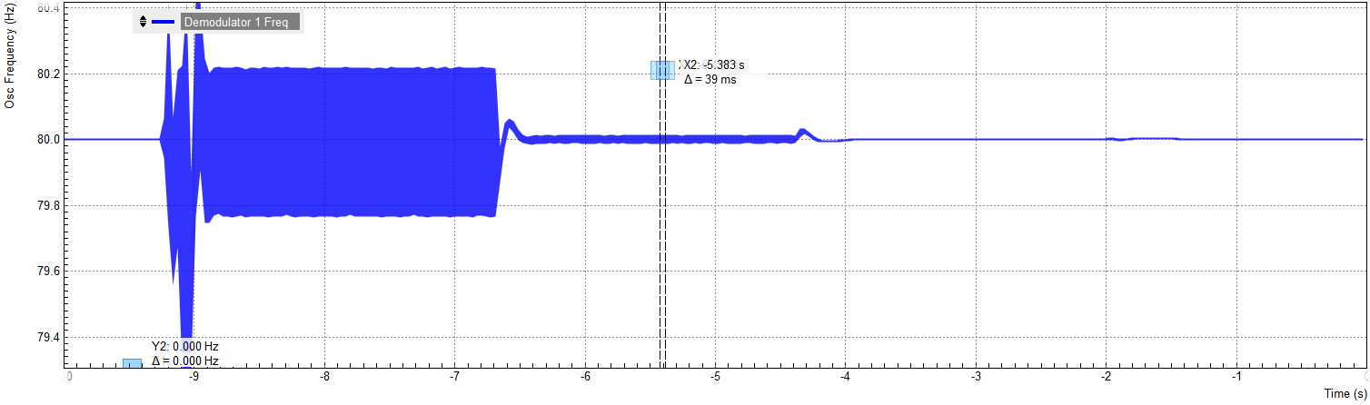
This mapping procedure is implemented with an automatic bandwidth adjustment that ensures quick locking over the whole instrument bandwidth. It covers a large variety of signal qualities in terms of frequency stability and signal-to-noise ratio. Over the course of automatic adjustment, the Low-Pass Filter bandwidth of the associated demodulators 2 or 4 usually ramps down until a final value is reached after a few seconds. The indicated bandwidth also marks an upper limit to the bandwidth of the phase-locked loop that does the mapping of the external signal to the internal oscillator. Figure 4 shows a typical result in the Plotter for the frequency tracking immediately after it is turned on. For such a measurement, open the Plotter tab and add the corresponding signal to the plot (Control sub-tab, Vertical Axis Groups, Frequency, Channel 1, Add Signal).
Note
With the MF-MD Multi-demodulator option installed, you can alternatively look at the phase error (Control sub-tab, Vertical Axis Groups, Demod Theta, Channel 2, Add Signal). Be sure to enable the corresponding data stream in the PC Data Transfer section of the corresponding Lock-in tab.
Measure at a Harmonic of the Reference Frequency
For our optical demonstration measurement, we use a Vishay TCRT5000 infrared detector/emitter pair whose light is passed through the optical chopper. The detector is a photo diode, the emitter a LED, and both are biased directly by the Auxiliary Output 2 through a simple circuit as shown in Figure 1. We current-bias the LED with 10 mA by applying 5 V across a 500 Ω resistor. The 1 kΩ resistor in series with the photo diode is merely a limiter. Note that the circuit by design can’t exceed the damage threshold of the MFLI (5 V on the 50 Ω I input).
The current generated by the photo diode contains an offset contribution, typically due to ambient light, and a modulation contribution due to the chopper. Both are in the range of some μA in our case, allowing us to use the higher input sensitivity of 100 μA instead of 10 mA and thus improve the input noise. The chopper wheel used for this experiment has a multiplier of 10, so the optical signal is actually modulated at a frequency of 800 Hz. This places us further away from the 50/60 Hz utility frequency without having to use a high revolution speed of the chopper.
We will use the harmonics functionality to internally generate an 800 Hz demodulation reference from the 80 Hz external reference. Setting this up again presents slight difference depending on the installed options, so we describe the required steps with and without installed MF-MD Multi-demodulator option.
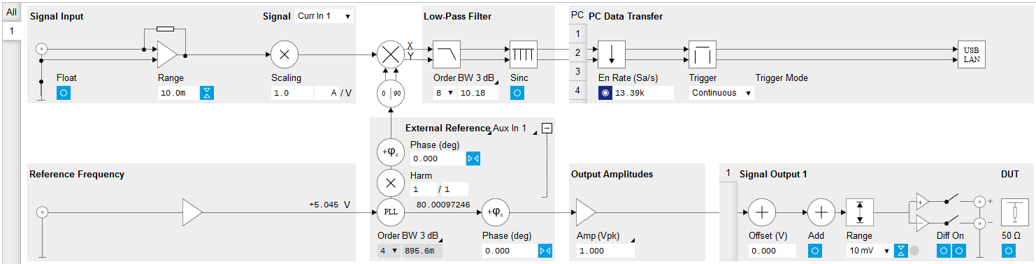
Without MF-MD Multi-demodulator option: In the Signal Input section of the graphical Lock-in tab, select Current Input 1 and change the input range to 100 μA. In the External Reference Section, set the Harmonic (Harm) to 10 / 1. Note that this setting is hidden by default. You can get access to this setting by expanding the section with a click on the + symbol on the top right of the section. You should now observe a numerical display of the demodulator reference frequency close to 800 Hz as shown in Figure 5. Finally, set the Low-Pass Filter to 100 Hz (3rd order) and enable the data stream in the PC Data Transfer section.
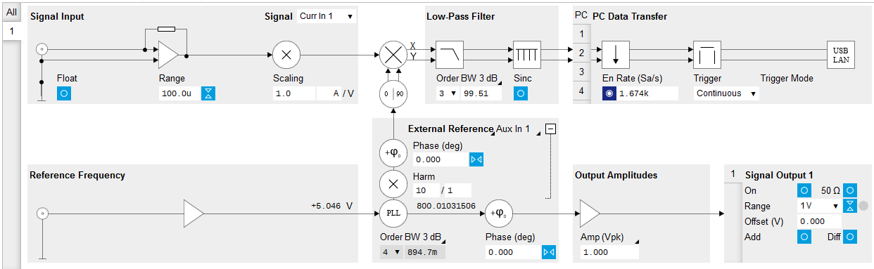
| Tab | Section | # | Label | Setting / Value / State |
|---|---|---|---|---|
| Lock-in | External Reference | 1 | Harm | 10 / 1 |
| Lock-in | Signal Input | 1 | Signal | Current Input 1 |
| Lock-in | Signal Input | 1 | Range | 100 μA |
frequency (without MF-MD option)
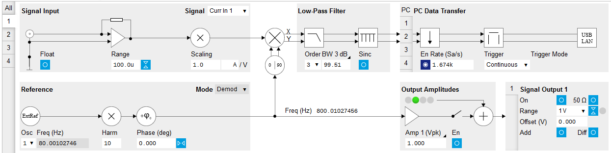
With MF-MD Multi-demodulator option: Open the graphical Lock-in tab of the first demodulator. We use this demodulator to perform the lock-in detection. In the Signal Input section of the graphical Lock-in tab, select Current Input 1 and change the input range to 100 μA. In the Reference section, choose Oscillator 1 and set the Harmonic (Harm) to 10, cf. Figure 6. In the circuit diagram of the graphical Lock-in tab, you should observe the numeric value of the demodulation frequency, 800 Hz. Set the Low-Pass Filter to 100 Hz (3rd order) and enable the data stream in the PC Data Transfer section.
| Tab | Section | # | Label | Setting / Value / State |
|---|---|---|---|---|
| Lock-in | Reference | 1 | Harm | 10 |
| Lock-in | Signal Input | 1 | Signal | Current Input 1 |
| Lock-in | Signal Input | 1 | Range | 100 μA |
frequency (with MF-MD option)
Note
The filter bandwidth should be well below the modulation frequency OMEGA in order to suppress the 2 OMEGA signal component (see Sinc Filtering). Here we use a filter bandwidth of 100 Hz at a modulation frequency OMEGA of 800 Hz.
Plot the Measurement Results
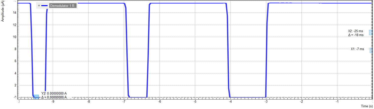
Having set up the demodulation at 800 Hz, we are ready to check the measurement data. Open the Plotter tab. In the Control sub-tab, select the Enabled Demods R setting in the Presets list. Figure 7 shows a plot of the photo diode current in which the light path between emitter and detector was manually intersected a number of times to show the measurement contrast. When the light path is open (except for the chopper wheel), we measure a constant rms current of about 15.5 μA, and whenever we block the light path the current drops to zero.