Lock-in Tab (MF-MD option)
This tab is the main lock-in amplifier control panel for MFLI Instruments with the MF-MD Multi-demodulator option installed. Users with instruments without this option installed are kindly referred to Lock-in Tab.
Features
- Functional block diagram with access to main input, output and demodulator controls
- Parameter table with main input, output and demodulator controls
- Controls for 4 individually configurable demodulators
- Auto ranging, scaling, arbitrary input units for both input channels
- Control for 4 oscillators
- Settings for main signal inputs and signal outputs
- Choice of reference source, trigger options and data transfer rates
Description
The Lock-in tab is the main control center of the instrument and open after start up by default. Whenever the tab is closed or an additional one of the same type is needed, clicking the following icon will open a new instance of the tab.
| Control/Tool | Option/Range | Description |
|---|---|---|
| Lock-in MD | Quick overview and access to all the settings and properties for signal generation and demodulation. |
The default view of the Lock-in tab is the parameter table view. It is accessible under the side tab labeled All and provides controls for all demodulators in the instrument. Moreover, for each individual demodulator there is a functional block diagram available. It is accessible under the side tab labeled with the corresponding demodulator number.
Parameter Table
The parameter table (see Figure 1) consists of 5 sections: Signal Inputs, Oscillators, Demodulators, Output Amplitudes and Signal Outputs. The Demodulator section contains 4 rows each of them providing access to the settings of one dual phase demodulator. Demodulators 2 and 4 can be used for external referencing. Every demodulator can be connected to any of the possible inputs and oscillators.
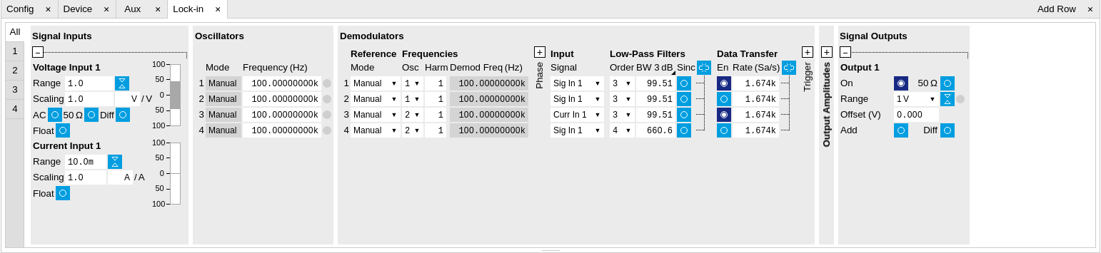
The Signal Inputs section allows the user to define all relevant settings specific to the signal entered as for example input coupling, range, etc. Some of the available options like phase adjustment and the trigger functionality are collapsed by default. It takes one mouse click on the "+" icon in order to expand those controls. On the right-hand side of the Lock-in tab the Signal Outputs section allows to define signal amplitudes, offsets and range values.
The Scaling field below the Range field can be used to multiply the Signal Input data for instance to account for the gain of an external amplifier. In case there is a transimpedance gain of 10 V/A applied to the input signal externally, then the Scaling field can be set to 0.1 and the Units field can be set to A in order to show the actual current readings through the entire user interface.
There are two buttons below the Scaling field that can be toggled: the AC/DC button and the 50 Ω/ 10 MΩ . The AC/DC button sets the coupling type: AC coupling has a high-pass cutoff frequency that can be used to block large DC signal components to prevent input signal saturation during amplification. The 50 Ω/ 10 MΩ button toggles the input impedance between low (50 Ω) and high (approx. 10 MΩ ) input impedance. With 50 Ω input impedance, one will expect a reduction of a factor of 2 in the measured signal if the signal source also has an output impedance of 50 Ω.
Note
The Signal Inputs can be set to float which means that the BNC connector shield is no longer connected to the instrument ground. This setting affects both the current input and the voltage input. It is recommended to discharge the test device before connecting or to enable this setting only after the signal source has been connected to the Signal Input in grounded mode.
The Oscillator section indicates the frequency of the 4 internal oscillators . Where the Mode indicator shows Manual the user can define the oscillator frequency manually defined by typing a frequency value in the field. In case the oscillator is referenced to an external source the Mode indicator will show ExtRef and the frequency field is set to read-only. External reference requires a PLL to do the frequency mapping onto an internal oscillator. Successful locking is indicated by a green light right next to the frequency field.
The next section contains the Demodulators settings. The block diagram displayed in Figure 2 indicates the main demodulator components and their interconnection. The understanding of the wiring is essential for successfully operating the instrument.

Every line in the Demodulators section represents one demodulator. The Mode column is read-only for all demodulators except 2 and 4, which can be to set to either internal reference (Demod) or external reference mode (ExtRef). When internal reference mode is selected, it is possible to demodulate the input signal with 4 demodulators simultaneously at 4 independent frequencies and using different filter settings. For external reference mode, one demodulator is used for the reference recovery and a few settings are greyed-out, and therefore 3 demodulators remain for simultaneous measurements. In the Input Signal column one defines the signal that is taken as input for the demodulator. A wide choice of signals can be selected: Signal Inputs, the Trigger Inputs, the Auxiliary Inputs and Auxiliary Outputs. This allows to use the instrument for many different measurement topologies.
For each demodulator an additional phase shift can be introduced to the associated oscillator by entering the phase offset in the Phase column. This phase is added both, to the reference channel and the output of the demodulator. Hence, when the frequency is generated and detected using the same demodulator, signal phase and reference phase change by the same amount and no change will be visible in the demodulation result. Demodulation of frequencies that are integer multiples of any of the oscillator frequencies is achieved by entering the desired factor in the Harm column. The demodulator readout can be obtained using the Numeric tab which is described in Numeric Tab.
In the middle of the Lock-in tab is the Low-Pass Filters section where the filter order can be selected in the drop down list for each demodulator and the filter bandwidth (BW 3dB) can chosen by typing a numerical value. Alternatively the time constant of the filter (TC) or the noise equivalent power filter bandwidth (BW NEP) can be chosen by clicking on the column’s header. For example, setting the filter order to 4 corresponds to a roll off of 24 dB/oct or 80 dB/dec i.e. an attenuation of 104 for a tenfold frequency increase. If the Low-Pass Filter bandwidth is comparable to or larger than the demodulation frequency, the demodulator output may contain frequency components at the frequency of demodulation and its higher harmonics. In this case, the additional Sinc Filter can be enabled. It attenuates those unwanted harmonic components in the demodulator output. The Sinc Filter is also useful when measuring at low frequencies, since it allows to apply a Low-Pass Filter bandwidth closer to the demodulation frequency, thus speeding up the measurement time.
The data transfer of demodulator outputs is activated by the En button in the Data Transfer section where also the sampling rate (Rate) for each demodulator can be defined.
The Trigger section next to the Data Transfer allows for setting trigger conditions in order to control and initiate data transfer from the Instrument to the host PC by the application of logic signals (e.g. TTL) to either Trigger Input 1 or 2 on the back panel.
The Output Amplitudes section is only available for Instruments with the MF-MD option installed and allows for the flexible adjustment of output amplitudes of different demodulators and their summation on the Signal Output. In order to avoid signal clipping the sum of amplitudes of each signal output needs to be smaller than the range defined in the Signal Outputs section on the right. By clicking the headline of each column one can switch between amplitude definitions in terms of root mean square values, peak-to-peak values or even units of dBm, when the 50 Ω option in the Signal Output section is activated. In the Signal Outputs section the On buttons allow to activate the Signal Output of the front panel. The Range drop down list is used to select the proper output range setting. On the Signal Output a digital offset voltage (Offset) can be defined. The maximum output signal permitted is ± 10 V.
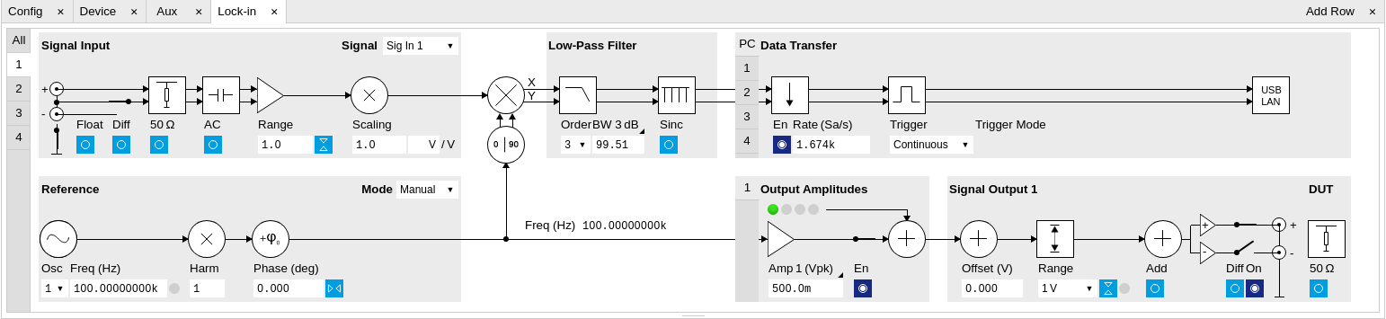
Block Diagram
The block diagram view of the main instrument functions is also sometimes called the "Graphical Lock-in Tab". Depending on how many demodulators are available in the instrument a set of numbered side tabs are available giving access to a Graphical Lock-in Tab for each demodulator. The block diagrams are fully functional and provide the user with a visual feedback of what is going on inside the instrument. All control elements that are available in the Parameter Table detailed in the previous section are also present in the graphical representation.
The block diagram in Figure 3 describes the signal path throughout the instrument for the case when the internal oscillator is used as reference. The Signal Inputs and Reference/Internal Frequency are described on the left side, the core of demodulation with the mixer and low-pass filter is located in the center of the tab and the Signal Outputs, the Auxiliary Outputs as well as the data transfer to the PC is sketched on the right.
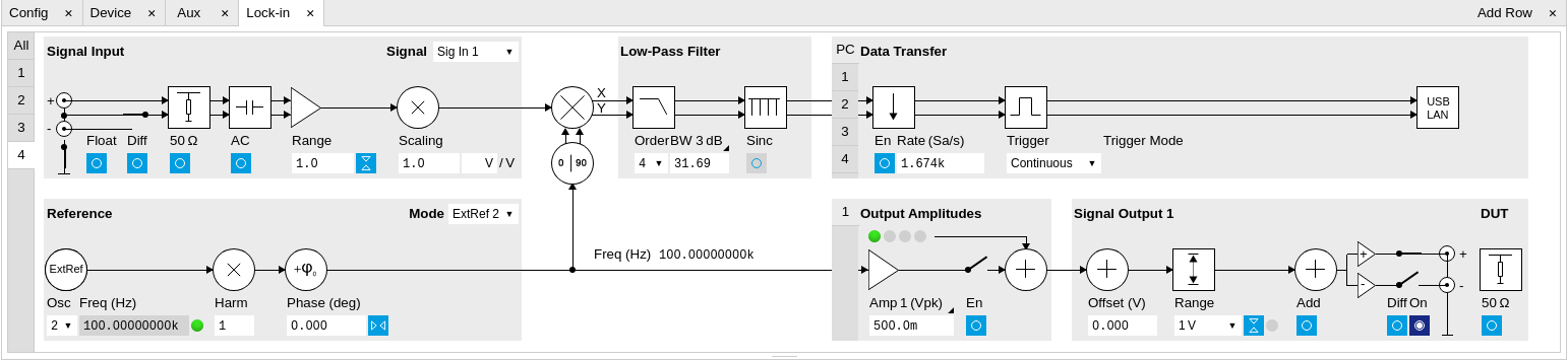
The block diagram in Figure 4 describes the signal path throughout the instrument for the case when an external reference is used. This setting is only available for demodulator 2/4. In order to map an external frequency to any of the oscillators, go to the Reference section of demodulator 2/4 and change the mode to ExtRef. This demodulator will then be used as a phase detector within the phase-locked loop. The software will choose the appropriate filter settings according to the frequency and properties of the reference signal. Once a demodulator is used to map an external frequency on to one of the internal oscillators, it is no longer available for other measurements.
Functional Elements
| Control/Tool | Option/Range | Description |
|---|---|---|
| Range | 3.0 mV, 10 mV, 30 mV, 100 mV, 300 mV, 1 V, 3.0 V | Defines the gain of the analog input amplifier. The range should exceed the incoming signal by roughly a factor two including a potential DC offset. The instrument selects the next higher available range relative to a value inserted by the user. A suitable choice of this setting optimizes the accuracy and signal-to-noise ratio by ensuring that the full dynamic range of the input ADC is used. |
| On | ON / OFF | Enable Signal Input. |
| Auto |  |
Automatic adjustment of the Range to about two times the maximum signal input amplitude measured over about 100 ms. |
| Scaling | numeric value | Applies an arbitrary scale factor to the input signal. |
| Measurement Unit | unit acronym | Defines the physical unit of the input signal. Use *, / and ^ operators, e.g., m or m/s^2. The value in this field modifies the readout of all measurement tools in the user interface. Typical uses of this field is to make measurements in the unit before the sensor/transducer, e.g. to take an transimpedance amplifier into account and to directly read results in Ampere instead of Volts. |
| Coupling | OFF: DC coupling | Defines the input coupling for the Signal Inputs. AC coupling inserts a high-pass filter. |
| ON: AC coupling | ||
| 50 Ω | OFF: 10 MΩ | Switches between 50 Ω (ON) and 10 MΩ (OFF). |
| ON: 50 Ω | ||
| Diff | ON: Differential voltage input | Switches between single ended (OFF) and differential (ON) measurements. |
| OFF: Single ended voltage input | ||
| Float | OFF: GND connected | Switches between floating (ON) and connected grounds (OFF). This setting applies both to the voltage and the current input. It is recommended to discharge the test device before connecting or to enable this setting only after the signal source has been connected to the Signal Input in grounded mode. |
| ON: Floating | ||
| Range | 10 mA | Defines the gain of the current input amplifier. The range should exceed the incoming signal by roughly a factor two including a potential DC offset. The instrument selects the next higher available range relative to a value inserted by the user. A suitable choice of this setting optimizes the accuracy and signal-to-noise ratio by ensuring that the full dynamic range of the input ADC is used. Ranges marked with an asterisk (*) are only available on instruments with serial numbers MF-DEV3200 and higher. |
| 1 nA (*) | ||
| 10 nA | ||
| 100 nA (*) | ||
| 1 µA | ||
| 10 µA (*) | ||
| 100 µA | ||
| 1 mA (*) | ||
| Auto | |
Automatic adjustment of the Range to about two times the maximum current input amplitude measured over about 100 ms. |
| Scaling | numeric value | Applies an arbitrary scale factor to the current input. |
| Measurement Unit | unit acronym | Defines the physical unit of the current input. Use *, / and ^ operators, e.g., m or m/s^2 The value in this field modifies the readout of all measurement tools in the user interface. |
| Mode | Indicates how the frequency of the corresponding oscillator is controlled (manual, external reference). Read only flag. | |
| Manual | The user setting defines the oscillator frequency. | |
| ExtRef | An external reference is mapped onto the oscillator frequency. | |
| Frequency (Hz) | 0 to 5 MHz | Frequency control for each oscillator. |
| Locked | ON / OFF | Oscillator locked to external reference when turned on. |
| Mode | Select the reference mode (manual or external reference) or indicate the unit that uses the demodulator (e.g. PLL). | |
| Manual | Default lock-in operating mode with manually set reference frequency. | |
| ExtRef | The demodulator is used for external reference mode and tracks the frequency of the selected reference input. The demodulator bandwidth is set automatically to adapt to the signal properties. | |
| ExtRef Low BW | The demodulator is used for external reference mode and tracks the frequency of the selected reference input. The demodulator bandwidth is fixed at low value. Use when automatic bandwidth adjustment interferes with a stable lock at a fixed frequency. | |
| ExtRef High BW | The demodulator is used for external reference mode and tracks the frequency of the selected reference input. The demodulator bandwidth is fixed at a high value. Use when automatic bandwidth adjustment interferes with tracking a strongly fluctuating frequency. | |
| PLL | The demodulator is used in PLL mode for frequency tracking of the signal. This function requires the MF-PID option. | |
| IA | The demodulator is used by the impedance analyzer. | |
| Osc | oscillator index | Connects the selected oscillator with the demodulator corresponding to this line. Number of available oscillators depends on the installed options. |
| Harm | 1 to 1023 | Multiplies the demodulator's reference frequency with the integer factor defined by this field. If the demodulator is used as a phase detector in external reference mode (PLL), the effect is that the internal oscillator locks to the external frequency divided by the integer factor. |
| Harm | 1 to 1023 | Divides the demodulator's reference frequency by an integer factor in external reference mode. |
| Demod Freq (Hz) | 0 to 5 MHz | Indicates the frequency used for demodulation and for output generation. The demodulation frequency is calculated with oscillator frequency times the harmonic factor. When the MF-MOD option is used linear combinations of oscillator frequencies including the harmonic factors define the demodulation frequencies. |
| Phase (deg) | -180° to 180° | Phase shift applied to the reference input of the demodulator. |
| Zero |  |
Adjust the phase of the demodulator reference automatically in order to read zero degrees at the demodulator output. This action maximizes the X output, zeros the Y output, zeros the Θ output, and leaves the R output unchanged. |
| Signal | Selects the signal source to be associated to the demodulator. | |
| Sig In 1 | Signal Input 1 is connected to the corresponding demodulator. | |
| Curr In 1 | Current Input 1 is connected to the corresponding demodulator. | |
| Trigger 1 | Trigger 1 is connected to the corresponding demodulator. | |
| Trigger 2 | Trigger 2 is connected to the corresponding demodulator. | |
| Aux Out 1 | Internal value of Auxiliary Output 1 is applied to the input of the corresponding demodulator. | |
| Aux Out 2 | Internal value of Auxiliary Output 2 is applied to the input of the corresponding demodulator. | |
| Aux Out 3 | Internal value of Auxiliary Output 3 is applied to the input of the corresponding demodulator. | |
| Aux Out 4 | Internal value of Auxiliary Output 4 is applied to the input of the corresponding demodulator. | |
| Aux In 1 | Auxiliary Input 1 is connected to the corresponding demodulator. | |
| Aux In 2 | Auxiliary Input 2 is connected to the corresponding demodulator. | |
| Constant | Demodulate a constant input. This results in a sine wave of the frequency specified by the demodulator's oscillator with an amplitude of 1 (at lower frequencies; higher frequencies will be attenuated). The maximum possible frequency is limited by the demodulator sampling rate and bandwidth; use demodulator order 1 for the least attenuation in demodulator output. This signal may be used with the auxiliary outputs, PID and Threshold Unit for advanced measurement and control tasks. When the demodulator output is written to an auxiliary output, the resulting signal can also be used as a second output channel (for low frequencies). | |
| Order | Selects the filter roll off between 6 dB/oct and 48 dB/oct. | |
| 1 | 1st order filter 6 dB/oct | |
| 2 | 2nd order filter 12 dB/oct | |
| 3 | 3rd order filter 18 dB/oct | |
| 4 | 4th order filter 24 dB/oct | |
| 5 | 5th order filter 30 dB/oct | |
| 6 | 6th order filter 36 dB/oct | |
| 7 | 7th order filter 42 dB/oct | |
| 8 | 8th order filter 48 dB/oct | |
| TC/BW Select | Defines the display unit of the low-pass filters: time constant (TC) in seconds, noise equivalent power bandwidth (BW NEP) in Hz, 3 dB bandwidth (BW 3 dB) in Hz. | |
| TC | Defines the low-pass filter characteristic using time constant (s) of the filter. | |
| BW NEP | Defines the low-pass filter characteristic using the noise equivalent power bandwidth (Hz) of the filter. | |
| BW 3 dB | Defines the low-pass filter characteristic using the 3 dB cut-off frequency (Hz) of the filter. | |
| TC/BW Value | numeric value | Defines the low-pass filter characteristic in the unit defined above. |
| Sinc | ON / OFF | Enables the sinc filter. Note that the sinc filter is only useful for very low-frequency measurements (<100 Hz); therefore, for high-frequency measurements, it must be switched off. When the filter bandwidth is comparable to or larger than the demodulation frequency, the demodulator output may contain frequency components at the frequency of demodulation and its higher harmonics. The sinc is an additional filter that attenuates these unwanted components in the demodulator output. |
| Filter Lock |  |
Makes all demodulator filter settings equal (order, time constant, bandwidth). Enabling the lock copies the settings from demodulator 1 to all other demodulators. With locked filters, any modification to a filter setting is applied to all other filters, too. Releasing the lock does not change any setting. |
| Enable Streaming | ON / OFF | Enables the data acquisition and streaming of demodulated samples to the host computer for the corresponding demodulator. The streaming rate is defined in the field on the right hand side. Enabling a stream activates a corresponding element in the numeric tab and allows for demodulated samples to be visualized and analyzed in any of the LabOne measurement tools. Note: increasing number of active demodulators increases load on physical connection to the host computer. |
| Rate (Sa/s) | 0.056 Sa/s to 857 kSa/s | Defines the demodulator sampling rate, the number of samples that are sent to the host computer per second. A rate of about 7-10 higher as compared to the filter bandwidth usually provides sufficient aliasing suppression. This is also the rate of data received by LabOne Data Server and saved to the computer hard disk. This setting has no impact on the sample rate on the auxiliary outputs connectors. Note: the value inserted by the user may be approximated to the nearest value supported by the instrument. |
| Demodulator Sampling Rate Lock | |
Makes all demodulator sampling rates equal. Enabling the lock copies the settings from demodulator 1 to all other demodulators. With locked sampling rates, any modification to a sampling rate is applied to all other sampling rate fields, too. Releasing the lock does not change any setting. |
| Trigger | Selects the acquisition mode of demodulated samples. Continuous trigger means data are streamed to the host computer at the Rate indicated. | |
| Continuous | Selects continuous data acquisition mode. The demodulated samples are streamed to the host computer at the Rate indicated on the left hand side. In continuous mode the numerical and plotter tools are continuously receiving and display new values. | |
| Trigger 1 | Selects external triggering by means of the Trigger 1 connector. Demodulated samples are sent to the host computer for each event defined in the Trig Mode field. When edge trigger is selected the rate field is greyed out and has no meaning. | |
| Trigger 2 | Selects external triggering by means of the Trigger 2 connector. Demodulated samples are sent to the host computer for each event defined in the Trig Mode field. When edge trigger is selected the rate field is greyed out and has no meaning. | |
| Trigger 1\|2 | Same functionality as above, but triggering is based on a logical OR function of Trigger 1 and Trigger 2. | |
| Trigger Mode | Defines the edge or level trigger mode for the selected Trigger input. Note: this field only appears when a non-continuous trigger is selected in the Trigger field. | |
| Rising | Selects triggered sample acquisition mode on rising edge of the selected Trigger input. | |
| Falling | Selects triggered sample acquisition mode on falling edge of the selected Trigger input. | |
| Both | Selects triggered sample acquisition mode on both edges of the selected Trigger input. | |
| High | Selects continuous sample acquisition mode on high level of the selected Trigger input. In this selection, the sample rate field determines the frequency in which demodulated samples are sent to the host computer. | |
| Low | Selects continuous sample acquisition mode on low level of the selected Trigger input. In this selection, the sample rate field determines the frequency in which demodulated samples are sent to the host computer. | |
| Amplitude Unit | Vpk, Vrms, dBm | Select the unit of the displayed amplitude value. The dBm value is only valid for a system with 50 Ω termination. |
| Amplitude Mode | Indicates the type or source of the waveform being generated. 'Sine' indicates a sinusoidal waveform from the internal oscillator. | |
| Amplitude Enable | ON / OFF | Enables individual output signal amplitude. When the MF-MD option is used, it is possible to generate signals being the linear combination of the available demodulator frequencies. |
| Amplitude (V) | -range to range | Defines the output amplitude for each demodulator frequency as rms or peak-to-peak value. A negative amplitude value is equivalent to a phase change of 180 degree. Linear combination of multiple amplitude settings on the same output are clipped to the range setting. Note: the value inserted by the user may be approximated to the nearest value supported by the Instrument. |
| On | ON / OFF | Main switch for the Signal Output corresponding to the blue LED indicator on the instrument front panel. |
| Load | ON / OFF | Select the impedance of external load. Once disabled, it assumes the load has a high impedance (Hi-Z). Once enabled, it assumes the load is 50 Ω for single-ended output or 100 Ω for differential output. The output impedance is always 50 Ω (single-ended) or 100 Ω (differential) regardless of the load impedance. For a load impedance of 50 Ω or 100 Ω the displayed voltage is half the output voltage to reflect the voltage seen on the load. |
| Range | Defines the maximum output voltage that is generated by the corresponding Signal Output. This includes the potential multiple Signal Amplitudes and Offsets summed up. Select the smallest range possible to optimize signal quality. This setting ensures that no levels or peaks above the setting are generated, and therefore it limits the values that can be entered as output amplitudes. Therefore selected output amplitudes are clipped to the defined range and the clipping indicator turns on. If 50 Ω target source or differential output is enabled the possible maximal output range will be half. |
|
| 10 mV | Selects output range ±10 mV. | |
| 100 mV | Selects output range ±100 mV. | |
| 1 V | Selects output range ±1 V. | |
| 10 V | Selects output range ±10 V. | |
| Auto Range | |
Selects the most suited output range automatically. |
| Output Clipping | grey/red | Indicates that the specified output amplitude(s) exceeds the range setting. Signal clipping occurs and the output signal quality is degraded. Adjustment of the range or the output amplitudes is required. |
| Offset | -range to range | Defines the DC voltage that is added to the dynamic part of the output signal. |
| Add | ON / OFF | The signal supplied to the Aux Input 1 is added to the signal output. For differential output the added signal is a common mode offset. |
| Diff | ON / OFF | Switch between single-ended output (OFF) and differential output (ON). In differential mode the signal swing is defined between Signal Output +V / -V. |