PLL Tab
The PLL tab allows convenient setup of a two independent phase-locked loop for high-speed tracking of frequency modulated signals. This tab is only available when the HF2-PLL Dual Phase-locked Loop option is installed on the HF2 Instrument (see Information section in the Device tab).
Note
Demodulators that are used by an active PLL are set to read-only values on the Lock-in tab.
Features
- Two fully programmable 50 MHz phased-locked loops
- Programmable PLL center frequency and phase setpoint
- 50 kHz PLL bandwidth
- Programmable PLL phase detector filter settings and PID controller parameters
- PLL Advisor for model-based parameter suggestion and transfer function analysis
- Auto-zero functions for center frequency and setpoint
- Advanced 2-ω PLL mode (requires HF2-MF option)
Description
The PLL tab offers a convenient way to set up a phase-locked loop. In this way the frequency of an external signal can be mapped onto one of the instrument’s internal oscillators. An advisor functionality based on mathematical models helps the user finding and optimizing the PID parameters and quickly optimizing the servo bandwidth for the application. Whenever the tab is closed or an additional one of the same type is needed, clicking the following icon will open a new instance of the tab.
| Control/Tool | Option/Range | Description |
|---|---|---|
| PLL | Features all control, analysis, and simulation capabilities of the phase-locked loops. |
The PLL tab (see Figure 1) is divided into two side-tabs corresponding to the two PLL units. It contains a settings section on the left and an advisor section with graphical display on the right.
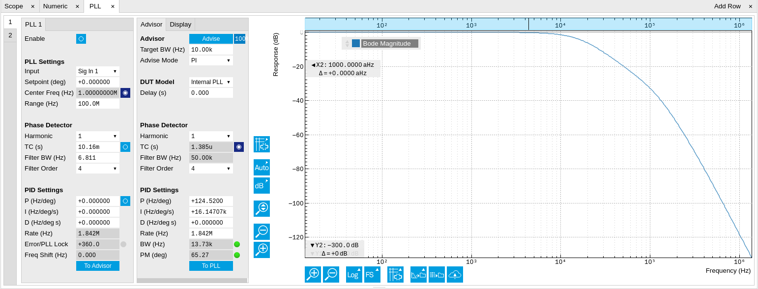
Figure 2 shows a block diagram of the PLL with its components, their interconnections and the variables to be specified by the user. The demodulator is slightly simplified for this sketch. Its full block diagram is given in Demodulator block diagram (without HF2-MF option) or Demodulator block diagram (HF2-MF option).

In a typical work flow to set up a PLL one would first define the center
frequency, frequency range, and the phase setpoint in the left section.
If the frequency is not know beforehand, it can often be measured using
the Sweeper or Spectrum tool. Then one would set a target bandwidth in
the Advisor sub-tab and subsequently click on the  button, and then enable the PLL. If the Error field now displays very
small values, the phase lock has been successful. One can now iterate
the process and e.g. play with the target bandwidth in the PLL Advisor
to calculate a new set of feedback parameters. Displaying the oscillator
frequency in the Plotter along with a Histogram and Math function (e.g.
standard deviation) can help to characterize residual phase deviations
and further improve lock performance by manual tweaking.
button, and then enable the PLL. If the Error field now displays very
small values, the phase lock has been successful. One can now iterate
the process and e.g. play with the target bandwidth in the PLL Advisor
to calculate a new set of feedback parameters. Displaying the oscillator
frequency in the Plotter along with a Histogram and Math function (e.g.
standard deviation) can help to characterize residual phase deviations
and further improve lock performance by manual tweaking.
Note
The frequency range in the PLL Settings section should exceed the target bandwidth by at least a factor of 5 to 10.
Note
PLL 1 uses demodulator 7 as phase detector, and PLL 2 uses demodulator 8. The Input selection determines which signal is connected to the corresponding demodulator. This setting is the same as the Input Signal setting in the Lock-in tab.
Functional Elements
| Control/Tool | Option/Range | Description |
|---|---|---|
| Enable | ON / OFF | Enable the PLL |
| Input | Sig In 1/2, Aux In 1/2, DIO D0/1 | Select the input signal of the PLL controller |
| Center Freq (Hz) | 0 to 50 MHz | Center frequency of the PLL oscillator. The PLL frequency shift is relative to this center frequency. |
| Auto Center Frequency | ON / OFF | The PLL Center Frequency is determined automatically. In this mode, the instrument sweeps the operating range until it finds a suitable frequency. Note: Auto Center Frequency works only for open loop systems. Closed loop systems require manual mode. |
| Range | numeric value | Set the frequency range of the PLL controller output relative to the center frequency |
| Harmonic | 1, 2 | Set the harmonic used in the phase detector. A setting of 2 means the PLL generates a sub-harmonic of the external reference. |
| TC (s) | numeric value | Filter time constant of the demodulator used as the phase detector. |
| Auto TC Enable | ON / OFF | When On, the PLL is running at full bandwidth. Use manual mode (off) for low-noise performance. |
| Filter BW (Hz) | numeric value | Filter bandwidth of the demodulator used as the phase detector. |
| Filter Order | 1-8 | Filter order of the demodulator used as the phase detector. |
| Setpoint (deg) | numeric value | Phase set point in degrees (i.e. PID setpoint). Controls the phase difference between the input signal and the generated signal. |
| Automated adjustment of PID coefficients | ON / OFF | If turned on together with Auto TC Enable and Auto Center Frequency, the PLL is in ExtRef mode |
| P | numeric value | PID proportional gain P |
| I/Ti | numeric value | Integral gain coefficient I or time constant Ti where Ti=P/I. |
| D/Td | numeric value | Derivative gain coefficient D or time constant Td where Td=D/P. |
| Rate (Hz) | numeric value | Current sampling rate of the PLL control loop. Note: The numerical precision of the controller is influenced by the loop filter sampling rate. If the target bandwidth is below 1 kHz is starts to make sense to adjust this rate to a value of about 100 to 500 times the target bandwidth. If the rate is set too high for low-bandwidth applications, integration inaccuracies can lead to nonlinear behavior. |
| Error (deg) | numeric value | Current phase error of the PLL (Set Point - PID Input). |
| PLL lock LED | grey/green | Indicates when the PLL is locked. The PLL error is sampled at 5 Sa/s and its RMS value is calculated. If the result is smaller than 5 degrees the loop is considered locked. |
| Freq Shift (Hz) | numeric value | Current frequency shift of the PLL (Oscillator Freq - Center Freq). |
| To Advisor |  |
Copy the current PLL settings to the PLL Advisor. |
| Control/Tool | Option/Range | Description |
|---|---|---|
| Advise |  |
Calculate PID coefficients based on application mode and given settings. Only PID coefficients specified with the advise mode are optimized. The Advise mode can be used incremental, means current coefficients are used as starting point for the optimization unless other model parameters are changed in-between. |
| Progress | The percentage of design algorithm already done when the Advisor is in progress. | |
| Target BW (Hz) | numeric value | Target bandwidth for the PLL closed loop feedback system which is used for the advising of the PID parameters. This bandwidth defines the trade-off between PLL speed and phase noise. |
| Advise Mode | Select the PID coefficients that are optimized. The other PID coefficients remain unchanged but are used during optimization. This enables holding selected coefficients at a fixed value while optimizing the rest. The advise time will increase significantly with the number of parameters to be optimized. |
|
| P | Only optimize the proportional gain. | |
| I | Only optimize the integral gain. | |
| PI | Only optimize the proportional and the integral gain. | |
| PID | Optimize the proportional, integral, and derivative gains. | |
| DUT Model | The model to use for the parameter calculation. | |
| Harmonic | 1 to 1023 | Multiplier of the for the reference frequency of the modelled demodulator. |
| TC (s) | numeric value | Defines the low-pass filter time constant of the selected demodulator input. |
| Auto Bandwidth | ON / OFF | Adjusts the demodulator bandwidth to fit best to the specified target bandwidth of the full system. If disabled, a demodulator bandwidth too close to the target bandwidth may cause overshoot and instability. In special cases the demodulator bandwidth can also be selected smaller than the target bandwidth. |
| Filter BW | numeric Value | Defines the low-pass filter characteristic of the selected demodulator input. |
| Filter Order | Selects the filter roll off between 6 dB/oct and 48 dB/oct of the modelled demodulator. | |
| 1 | 1st order filter 6 dB/oct | |
| 2 | 2nd order filter 12 dB/oct | |
| 3 | 3rd order filter 18 dB/oct | |
| 4 | 4th order filter 24 dB/oct | |
| 5 | 5th order filter 30 dB/oct | |
| 6 | 6th order filter 36 dB/oct | |
| 7 | 7th order filter 42 dB/oct | |
| 8 | 8th order filter 48 dB/oct | |
| P | numeric value | Proportional gain P coefficient used for calculation of the response of the PID model. The parameter can be optimized with PID advise or changed manually. The parameter only gets active on the PID after pressing the button To PLL. |
| I/Ti | numeric value | Integral gain coefficient I or time constant Ti=P/I used for calculation of the response of the PID model. The parameter can be optimized with PID advise or changed manually. The parameter only gets active on the PID after pressing the button To PLL. |
| D/Td | numeric value | Integral gain coefficient D or time constant Td=D/P used for calculation of the response of the PID model. The parameter can be optimized with PID advise or changed manually. The parameter only gets active on the PID after pressing the button To PLL. |
| Rate (Hz) | RT load dependent | PID sampling rate used for simulation. The advisor will update the rate to match with the specified target bandwidth. A sampling rate close to the target bandwidth and excessive higher bandwidth will results in a simulation mismatch. |
| BW (Hz) | numeric value | Simulated bandwidth of the full close loop PLL with the current PID settings. This value should be larger than the target bandwidth. |
| Target BW LED | green/red | Green indicates that the target bandwidth can be achieved. For very high PLL bandwidth the target bandwidth might be only achieved using marginal stable PID settings. |
| PM (deg) | numeric value | Simulated phase margin of the PID with the current settings. The phase margin should be greater than 45 deg for stable conditions. An Infinite value is shown if no unity gain crossing is available to determine a phase margin. |
| Stable LED | green/red | Green indicates that the phase margin is fulfilled and the PID system should be stable. |
| To PLL | |
Copy the PLL Advisor settings to the PLL. |
| Control/Tool | Option/Range | Description |
|---|---|---|
| Advanced | ON / OFF | Enables manual selection of display and advice properties. If disabled the display and advise settings are automatically with optimized default values. |
| Display | Select the display mode used for rendering the system frequency or time response. | |
| Bode Magnitude | Display the Bode magnitude plot. | |
| Bode Phase | Display the Bode phase plot. | |
| Step Resp | Display the step response plot. | |
| Start (Hz) | numeric value | Start frequency for Bode plot display. For disabled advanced mode the start value is automatically derived from the system properties and the input field is read-only. |
| Stop (Hz) | numeric value | Stop frequency for Bode plot display. For disabled advanced mode the stop value is automatically derived from the system properties and the input field is read-only. |
| Start (s) | numeric value | Start time for step response display. For disabled advanced mode the start value is zero and the field is read-only. |
| Stop (s) | numeric value | Stop time for step response display. For disabled advanced mode the stop value is automatically derived from the system properties and the input field is read-only. |
| Response In | Start point for the plant response simulation for open or closed loops. In closed loop configuration all elements from output to input will be included as feedback elements. | |
| Demod Input | Start point is at the demodulator input. | |
| Setpoint | Start point is at the setpoint in front of the PID. | |
| PID Output | Start point is at PID output. | |
| Instrument Output | Start point is at the instrument output. | |
| DUT Output | Start point is at the DUT output and instrument input. | |
| Response Out | End point for the plant response simulation for open or closed loops. In closed loop configuration all elements from output to input will be included as feedback elements. | |
| PID Output | End point is at PID output. | |
| Instrument Output | End point is at the instrument output. | |
| DUT Output | End point is at the DUT output and instrument input. | |
| Demod Input | End point is at the demodulator input. | |
| System Output | End point is in front of the PID error calculation (Setpoint-System Output). | |
| Closed-Loop | ON / OFF | Switches the display of the system response between closed or open loop. |