Generate and Acquire a Test Signal
Note
This tutorial is applicable to all UHFQA Instruments.
Goals and Requirements
This tutorial explains how to generate and measure a simple pulsed signal with the AWG and the Monitoring Scope in the Quantum Analyzer Input tab.
The measurements in this tutorial can be performed using simple loop back connections.
Preparation
Connect the cables as illustrated below. Make sure that the UHF unit is powered on and connected by USB to your host computer or by Ethernet to your local area network (LAN) where the host computer resides. After starting LabOne the default web browser opens with the LabOne graphical user interface.

The tutorial can be started with the default instrument configuration (e.g. after a power cycle) and the default user interface settings (e.g. as is after pressing F5 in the browser).
Test Signal Generation
First, we enable both outputs of the UHF instrument.
| Tab | Sub-tab | Section | # | Label | Setting / Value / State |
|---|---|---|---|---|---|
| In / Out | Signal Outputs | 1 | On | ON | |
| In / Out | Signal Outputs | 2 | On | ON |
Copy the following code into the Sequence Editor in the AWG tab.
const LENGTH = 4096;
wave w = gauss(LENGTH, LENGTH/2, LENGTH/8);
var loop_cnt = getUserReg(0);
var wait_time = 0;

repeat (loop_cnt) {
  playWave(w, -w);
  startQA(QA_INT_NONE, true);
  playZero(LENGTH);
}
Upload this sequence program to the AWG of the UHFQA by clicking on
"Save" or "To Device". This program will generate a series of
dual-channel Gaussian pulses. The repetition number is defined by the
integer variable loop_cnt. To make it possible to control the
repetition number through the user interface, we use one of the User
Registers rather than to write this number into the program.
Apply the settings in the following table in order to configure the AWG output as well as the User Register.
| Tab | Sub-tab | Section | # | Label | Setting / Value / State |
|---|---|---|---|---|---|
| AWG | Control | Rerun | OFF | ||
| AWG | Control | Output 1 | Amplitude (FS) | 1.0 | |
| AWG | Control | Output 1 | Mode | Plain | |
| AWG | Control | Output 2 | Amplitude (FS) | 1.0 | |
| AWG | Control | Output 2 | Mode | Plain | |
| AWG | Control | User Registers | Register 1 | 64 |
Configure the QA setup tab
In the Quantum Analyzer Setup tab, apply the setting in the table below.
| Tab | Sub-tab | Section | # | Label | Setting / Value / State |
|---|---|---|---|---|---|
| QA Setup | Deskew | Delay (sample) | 200 |
This setting configures the trigger delay of the monitor, so that the generated signal is correctly aligned with the acquisition window.
Configure the Input Monitor
In the Quantum Analyzer Input tab, apply the settings in the table below.
| Tab | Sub-tab | Section | # | Label | Setting / Value / State |
|---|---|---|---|---|---|
| QA Input | Control | Input Monitor | Length | 4096 | |
| QA Input | Control | Input Monitor | Averages | 64 | |
| QA Input | Control | Run / Stop | ON |
In the AWG tab, click on "Start/Stop" in order to run the AWG. The line
startQA(QA_INT_NONE, true); triggers the Input Monitor acquisition.
See
Architecture and Signalling
for an overview of the different functional blocks and internal trigger
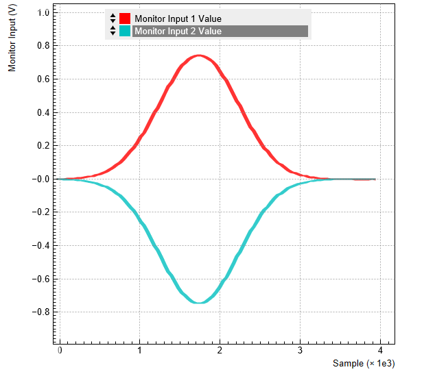
lines. 64 consecutive dual-channel pulses are acquired, averaged, and
displayed. The figure below shows the signal as displayed in the QA
Input tab. We denote the raw input signals (without averaging) as
V1(t) and V2(t).
Note
The Input Monitor Averages setting must agree with the number of Input
Monitor triggers generated by the AWG in one measurement burst (here
this is determined by the User Register 1 equal to the sequencer
variable loop_cnt. If the AWG generates more triggers than that, which
is e.g. the case when AWG Rerun would be enabled, the Input Monitor may
not be able to process and transmit all data in time, and may deliver
corrupted data to the computer.