Architecture and Signalling
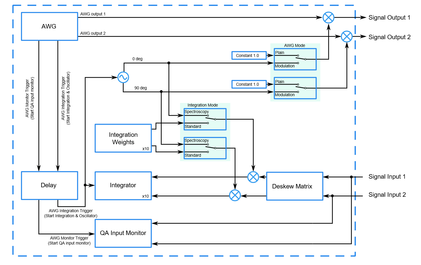
The UHFQA contains a number of functional blocks for signal generation and acquisition:
- The Arbitrary Waveform Generator represented in the AWG Tab
- The QA Input Monitor represented in the Quantum Analyzer Input Tab
- The QA Result Logger represented in the Quantum Analyzer Result Tab
- The Integration Units represented in the Quantum Analyzer Setup Tab
- The integration weight memory that can be configured and displayed in the Quantum Analyzer Input Tab
- The internal digital oscillator represented in the Inputs/Outputs Tab
- The internal trigger delay block represented in the Quantum Analyzer Setup Tab
Many of these blocks can operate independently and can be synchronized with external signals via the trigger inputs and outputs. In order to control the relative timing of the signal processing in these different blocks, internal trigger signals are used. Namely, the Arbitrary Waveform Generator can issue trigger signals in order to start the integration units, the input monitor, or the internal oscillator. The following block diagram gives an overview of the interconnection of these different blocks and illustrates the function of key user interface settings found in the user interface tabs listed above.
