Device Tab
The Device tab is the main settings tab for the connected instrument and is available on all UHFQA instruments.
Features
- Option and upgrade management
- External clock referencing (10 MHz)
- Auto calibration settings
- Instrument connectivity parameters
- Device monitor
Description
The Device tab serves mainly as a control panel for all settings specific to the instrument that is controlled by LabOne in this particular session. Whenever the tab is closed or an additional one of the same type is needed, clicking the following icon will open a new instance of the tab.
| Control/Tool | Option/Range | Description |
|---|---|---|
| Device | Provides instrument specific settings. |
The Device tab (see LabOne UI: Device tab) is divided into five sections: general instrument information, configuration, communication parameters, device presets, and a device monitor.
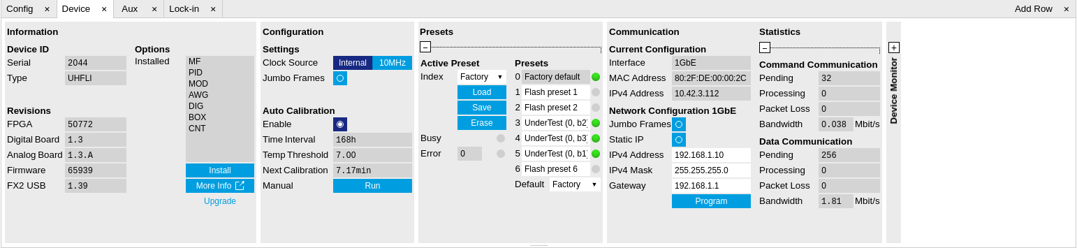
The Information section provides details about the instrument hardware and indicates the installed upgrade options. This is also the place where new options can be added by entering the provided option key.
The Configuration section allows one to change the reference from the internal clock to an external 10 MHz reference. The reference is to be connected to the Clock Input on the instrument back panel.
The Presets section allows you to define a custom instrument start-up configuration different from the factory default. This configuration is stored in the instrument itself and are applied independently of the control PC. This saves time in cases where the control PC is not routinely needed, for instance when using only analog interfaces the instrument configuration is fixed.
The Communication section offers access to the instruments TCP/IP settings.
Note
Activating Jumbo Frames is essential to achieve maximum data rates and also reduces load on the host PC.
The Statistics section gives an overview on communication statistics. In particular the current data rate (Bandwidth) that is consumed.
Note
Packet loss on data streaming over UDP or USB: data packets may be lost if total bandwidth exceeds the available physical interface bandwidth. Data may also be lost if the host computer is not able to handle high-bandwidth data. Network card setting optimization and Jumbo frame enabling may increase the maximal effective bandwidth.
Note
Packet loss on command streaming over TCP or USB: command packets should never be lost as it creates an invalid state.
The Device Monitor section is collapsed by default and generally only needed for servicing. It displays vitality signals of some of the instrument’s hardware components.
Self Calibration
Note
The calibration routine takes about 200 ms for that time the transfer of measurement data is stopped. That will lead to the following visible effects on the UI: - missing data on the plotter - the UI will shortly freeze - the data loss flag will not report data loss (as the server intentionally trashed data) - Sweeper, Data Acquisition tool and Scope will behave as usual and wait until they get data again - The Spectrum tool will restart as it can only analyze continuously sampled data
Please see also additional remarks regarding calibration in specifications.
Functional Elements
| Control/Tool | Option/Range | Description |
|---|---|---|
| Serial | 1-4 digit number | Device serial number |
| Type | string | Device type |
| FPGA | integer number | HDL firmware revision. |
| Digital Board | version number | Hardware revision of the FPGA base board. |
| Analog Board | version indicator | Hardware revision of the analog board. |
| Firmware | integer number | Revision of the device internal controller software. |
| FX2 USB | version number | USB firmware revision. |
| Installed Options | short names for each option | Options that are installed on this device. |
| Install |  |
Click to install options on this device. Requires a unique feature code and a power cycle after entry. |
| More Information | Display additional device information in a separate browser tab. | |
| Upgrade Device Options | Display available upgrade options. | |
| Clock Source | 10MHz reference clock source. | |
| Internal | The internal 10MHz clock is used as the frequency and time base reference. | |
| External | An external 10MHz clock is intended to be used as the frequency and time base reference. Provide a clean and stable 10MHz reference to the appropriate back panel connector. | |
| Jumbo Frames | ON / OFF | Enables jumbo frames (4k) on the TCP/IP interface. This will reduce the load on the PC and is required to achieve maximal throughput. Make sure that jumbo frames (4k) are enabled on the network card as well. If one of the devices on the network is not able to work with jumbo frames, the connection will fail. |
| Enabled | ON / OFF | Enables an automatic instrument self calibration about 16 min after start up. In order to guarantee the full specification, it is recommended to perform a self calibration after warm-up of the device. |
| Time interval | time | Time interval for which the self calibration is valid. After this time it is recommended to rerun the auto calibration. A LED indicator in the status bar indicates when another self calibration is recommended. |
| Calibration Temperature Threshold | temperature in °C | When the temperature changes by the specified amount, it is recommended to rerun the self calibration. A LED indicator in the status bar indicates when another self calibration is recommended. |
| Next calibration | time | Remaining time until the first calibration is executed or a recalibration is requested. |
| Manual self calibration |  |
Initiate self calibration to improve input digitizer linearity. |
| Index | Select between factory preset or presets stored in internal flash memory. | |
| Factory | Select factory preset. | |
| Flash 1-6 | Select one of the presets stored in internal flash memory 1-6. | |
| Load |  |
Load the selected preset. |
| Save |  |
Save the actual setting as preset. |
| Erase |  |
Erase the selected preset. |
| Busy | grey/red | Indicates that the device is busy with either loading, saving or erasing a preset. |
| Error | Returns a 0 if the last preset operation was successfully completed or 1 if the last preset operation was illegal. | |
| 0 | Last preset operation was successfully completed. | |
| 1 | Last preset operation was illegal. | |
| Error LED | grey/red | Turns red if the last operation was illegal. |
| Valid LED | grey/green | Turns green if a valid preset is stored at the respective location. |
| Presets | Shows a list of available presets including factory preset. | |
| 0 | Factory default preset. The name of the factory default preset is given and can not be edited. | |
| 1 | Flash preset 1. The name of this preset can be edited. | |
| 2 | Flash preset 2. The name of this preset can be edited. | |
| 3 | Flash preset 3. The name of this preset can be edited. | |
| 4 | Flash preset 4. The name of this preset can be edited. | |
| 5 | Flash preset 5. The name of this preset can be edited. | |
| 6 | Flash preset 6. The name of this preset can be edited. | |
| Default | Indicates the preset which is used as default preset at start-up of the device. | |
| Factory | Select factory preset as default preset. | |
| Flash 1-6 | Select one of the presets stored in internal flash memory 1-6 as default preset. | |
| Interface | 1. USB, 2. 1GbE | Active interface between device and data server. In case multiple options are available, the priority as indicated on the left applies. |
| MAC Address | 80:2F:DE:xx:xx:xx | MAC address of the device. The MAC address is defined statically, cannot be changed and is unique for each device. |
| IPv4 Address | default 192.168.1.10 | Current IP address of the device. This IP address is assigned dynamically by a DHCP server, defined statically, or is a fall-back IP address if the DHCP server could not be found (for point to point connections). |
| Jumbo Frames | ON / OFF | Enable jumbo frames for this device and interface as default. |
| Static IP | ON / OFF | Enable this flag if the device is used in a network with fixed IP assignment without a DHCP server. |
| IPv4 Address | default 192.168.1.10 | Static IP address to be written to the device. |
| IPv4 Mask | default 255.255.255.0 | Static IP mask to be written to the device. |
| Gateway | default 192.168.1.1 | Static IP gateway |
| Save |  |
Click to save the specified IPv4 address, IPv4 Mask and Gateway to the device. Otherwise, the settings will be lost after power cycling the device. |
| Pending | integer value | Number of buffers ready for receiving command packets from the device. |
| Processing | integer value | Number of buffers being processed for command packets. Small values indicate proper performance. For a TCP/IP interface, command packets are sent using the TCP protocol. |
| Packet Loss | integer value | Number of command packets lost since device start. Command packets contain device settings that are sent to and received from the device. |
| Bandwidth | numeric value | Command streaming bandwidth usage on the physical network connection between device and data server. |
| Pending | integer value | Number of buffers ready for receiving data packets from the device. |
| Processing | integer value | Number of buffers being processed for data packets. Small values indicate proper performance. For a TCP/IP interface, data packets are sent using the UDP protocol. |
| Packet Loss | integer value | Number of data packets lost since device start. Data packets contain measurement data. |
| Bandwidth | numeric value | Data streaming bandwidth usage on the physical network connection between device and data server. |
| FW Load | numeric value | Indicates the CPU load on the processor where the firmware is running. |