Functional Overview
This chapter provides the overview of the features provided by the UHF Instrument. The first section contains the description of the graphical overview and the hardware and software feature list. The next section details the front panel and the back panel of the measurement instrument. The following section provides product selection and ordering support.
Features

The UHF Instrument according to Figure 1 consists of several internal units (light blue color) surrounded by several interface units (dark blue color) and the front panel on the left-hand side and the back panel on the right-hand side. The arrows between the panels and the interface units indicates selected physical connections and the data direction flow.
The signal to be measured is usually connected to one of the two UHF signal inputs where it is amplified to a defined range and digitized at very high speed. The resulting samples are fed into the digital signal processor consisting of a qubit measurement unit with 10 parallel measurement channels . The output of the digital signal processor flow into a digital interface to be transferred to a host computer (LAN and USB interfaces) . Two low-distortion UHF signal outputs provide the signal generator functionality for arbitrary waveform generator output.
The Cross-Trigger Engine handles trigger exchange between the UHF-AWG Arbitrary Waveform Generator and the Qubit Measurement Unit. Internal triggers are used to trigger the Integration and Monitoring Scope.
Qubit Measurement Unit
- Dual-channel signal deskew
- 10 dual-channel integrators with programmable integration weight memory
- Complex rotation of integrated signals
- Crosstalk Suppression matrix
- Threshold operation
- Cross-correlation of integrated signals
- Cross-correlation of discretized measurement results
- Input Monitor averaging scope
- Statistics Unit for pattern analysis
- Result Logger
Ultra-high-frequency Signal Inputs
- 2 low-noise UHF inputs, single-ended, 600 MHz bandwidth
- Variable input range
- Switchable input impedance
- Selectable AC/DC coupling
Ultra-high-frequency Signal Outputs
- 2 low-distortion UHF outputs, single-ended, 600 MHz bandwidth
- Variable output range
AWG Features
- Sequencing and conditional branching
- Amplitude Modulation mode
- Parametric Sweeper
- High-level programming with LabOne AWG Sequencer
- 4-channel output mode
Auxiliary Input and Outputs
- 4 auxiliary outputs, user defined signals
- 2 auxiliary inputs, general purpose
High-speed Connectivity
- USB 2.0 high-speed 480 Mbit/s host interface
- LAN 1 Gbit/s controller interface
- DIO: 32-bit digital input-output port
- ZCtrl: 2 ports peripheral control
- Clock input connector (10 MHz)
- Clock output connector (10 MHz)
Software Features
- Web-based, high-speed user interface with multi-instrument control
- Data server with multi-client support
- API for C, LabVIEW, MATLAB, Python based instrument programming
Front Panel Tour
The front panel BNC connectors and control LEDs are arranged as shown in Figure 2 and listed in Table 1.

| Position | Label / Name | Description |
|---|---|---|
| A | Signal Input 1 | single-ended UHF input |
| B | Signal Input 1 Over | this red LED indicates that the input signal saturates the A/D converter and therefore the input range must be increased or the signal must be attenuated |
| C | Signal Input 2 | single-ended UHF input |
| D | Signal Input 2 Over | this red LED indicates that the input signal saturates the A/D converter and therefore the input range must be increased or the signal must be attenuated |
| E | Signal Output 1 | single-ended UHF output |
| F | Signal Output 1 ON | this blue LED indicates that the signal output is actively driven by the instrument |
| G | Signal Output 2 | single-ended UHF output |
| H | Signal Output 2 ON | this blue LED indicates that the signal output is actively driven by the instrument |
| I | Trigger 1 | analog reference input, TTL reference output, AWG marker output, or bidirectional digital TTL trigger |
| J | Trigger 2 | analog reference input, TTL reference output, AWG marker output, or bidirectional digital TTL trigger |
| K | Aux Output 1 | this connector provides a user defined signal, often used to output lock-in signals X, Y, R, Θ, or to output AWG signals |
| L | Aux Output 2 | this connector provides a user defined signal, often used to output lock-in signals X, Y, R, Θ, or to output AWG signals |
| M | Aux Output 3 | this connector provides a user defined signal, often used to output lock-in signals X, Y, R, Θ, or to output AWG signals |
| N | Aux Output 4 | this connector provides a user defined signal, often used to output lock-in signals X, Y, R, Θ, or to output AWG signals |
| O | Power | this LED indicates that the instrument is powered |
| color blue: the device has an active connection over USB or Ethernet | ||
| color orange: indicates ready to connect. The device is ready for connection over USB or Ethernet. The internal auto calibration process is also indicated by an orange LED | ||
| color orange blinking: device is in start-up mode and waiting for an IP address. As long as the device does not have a dynamic IP address or does use its static default address a connection attempt over Ethernet will fail |
Back Panel Tour
The back panel is the main interface for power, control, service and connectivity to other ZI instruments. Please refer to Figure 3 and Table 2 for the detailed description of the items.

| Position | Label / Name | Description |
|---|---|---|
| A | - | ventilator (important: keep clear from obstruction) |
| B | - | ventilator (important: keep clear from obstruction) |
| C | Power inlet | power inlet with ON/OFF switch |
| D | Earth ground | 4 mm banana jack connector for earth ground, electrically connected to the chassis and the earth pin of the power inlet |
| E | DIO | 32-bit digital input/output connector |
| F | X2 10GbE | 10 Gbit LAN connector |
| G | LAN 1GbE | 1 Gbit LAN connector |
| H | Clk 10 MHz In | clock input (10 MHz) for synchronization with other instruments |
| I | Clk 10 MHz Out | clock output (10 MHz) for synchronization with other instruments |
| J | USB | universal serial bus host computer connection |
| K | Trigger Out 3 | digital TTL trigger and AWG marker output - note: some UHF Instruments indicate Trigger 1 on the back panel instead of Trigger 3 |
| L | Trigger Out 4 | digital TTL trigger and AWG marker output - note: some UHF Instruments indicate Trigger 2 on the back panel instead of Trigger 4 |
| M | Trigger In 3 | digital trigger input - note: some UHF Instruments indicate Trigger 1 on the back panel instead of Trigger 3 |
| N | Trigger In 4 | digital trigger input - note: some UHF Instruments indicate Trigger 2 on the back panel instead of Trigger 4 |
| O | Aux In 1 | auxiliary input |
| P | Aux In 2 | auxiliary input |
| Q | ZCtrl 1 | peripheral pre-amplifier power & control bus. Attention: this is not an Ethernet plug, connection to an Ethernet network might damage the instrument |
| R | ZCtrl 2 | peripheral pre-amplifier power & control bus. Attention: this is not an Ethernet plug, connection to an Ethernet network might damage the instrument |
Ordering Guide
Table 3 provides an overview of the available UHFQA products. Upgradeable features are options that can be purchased anytime without need to send the Instrument to Zurich Instruments.
| Product code | Product name | Description | Field upgrade possible |
|---|---|---|---|
| UHFQA | UHFQA Quantum Analyzer | base product | - |
| UHF-AWG | UHF-AWG Arbitrary Waveform Generator | functionality included in base product | - |
| UHF-DIG | UHF-DIG Digitizer | option | yes |
| UHF-RUB | UHF-RUB Rubidium Atomic Clock | option | no |
DIOLink cable set
When using the HDAWG and the UHFQA in a Zurich Instruments Quantum Computing Control System, the two instruments need to be connected with a VHDCI cable between their respective DIO ports. Due to the different voltage levels of the DIO connectors on the HDAWG and UHFQA, a passive voltage level shifter needs to be placed in series with the VHDCI connection. It is furthermore recommended to use a mechanical stabilization of the VHDCI connection on the HDAWG side in order to prevent damage to the DIO connector due to cable pull. A set of a VHDCI cable, a level shifter, and a mechanical stabilization part are available as DIO Link Set from Zurich Instruments upon request under support@zhinst.com. The DIO Link Set is shown in the the figure below.
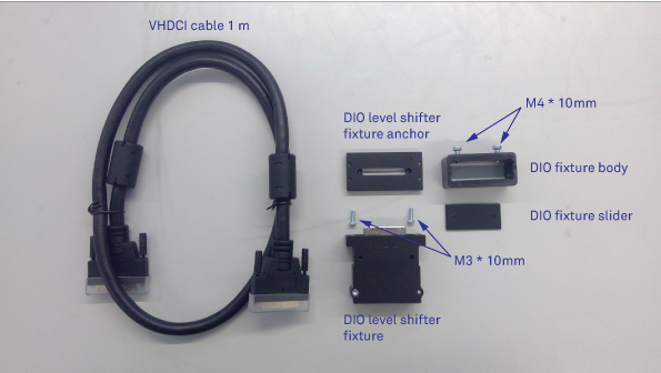
Please follow the instructions below in order to install the DIO Link Set between the HDAWG and the UHFQA.
-
Fix the DIO level shift fixture anchor to the DIO connector on the UHFQA using the screws already installed on the UHFQA DIO port.
-
Fix the DIO level shifter fixture to the anchor using the two M3*10 mm screws.
-
Clamp the DIO fixture (slider and body) lightly to one of the connectors of the VHDCI cable using the two M4*10 mm screws. This side of the cable is to be connected to the HDAWG.
-
Connect the VHDCI cable between the DIO level shifter fixture and the DIO port on the HDAWG and tighten the manual screws on both VHDCI connectors.
-
Push the DIO fixture (slider and body) firmly towards the HDAWG casing and tighten the two M4*10 mm screws to increase the mechanical stability of the VHDCI cable connection.