Skip to content

Device Node Tree

This chapter contains reference documentation for the settings and measurement data available on MFIA Instruments. Whilst Functional Description LabOne User Interface describes many of these settings in terms of the features available in the LabOne User Interface, this chapter describes them on the device level and provides a hierarchically organized and comprehensive list of device functionality.

Since these settings and data streams may be written and read using the LabOne APIs (Application Programming Interfaces) this chapter is of particular interest to users who would like to perform measurements programmatically via LabVIEW, Python, MATLAB, .NET or C.

Please see: - Introduction for an introduction of how the instrument’s settings and measurement data are organized hierarchically in the Data Server’s so-called "Node Tree". - Reference Node Documentation for a reference list of the settings and measurement data available on MFIA Instruments, organized by branch in the Node Tree.

Introduction

This chapter provides an overview of how an instrument’s configuration and output is organized by the Data Server.

All communication with an instrument occurs via the Data Server program the instrument is connected to (see LabOne Software Architecture for an overview of LabOne’s software components). Although the instrument’s settings are stored locally on the device, it is the Data Server’s task to ensure it maintains the values of the current settings and makes these settings (and any subscribed data) available to all its current clients. A client may be the LabOne User Interface or a user’s own program implemented using one of the LabOne Application Programming Interfaces, e.g., Python.

The instrument’s settings and data are organized by the Data Server in a file-system-like hierarchical structure called the node tree. When an instrument is connected to a Data Server, its device ID becomes a top-level branch in the Data Server’s node tree. The features of the instrument are organized as branches underneath the top-level device branch and the individual instrument settings are leaves of these branches.

For example, the auxiliary outputs of the instrument with device ID "dev2006" are located in the tree in the branch:

/dev1000/auxouts/

In turn, each individual auxiliary output channel has its own branch underneath the "AUXOUTS" branch.

/dev1000/auxouts/0/
/dev1000/auxouts/1/
/dev1000/auxouts/2/
/dev1000/auxouts/3/

Whilst the auxiliary outputs and other channels are labelled on the instrument’s panels and the User Interface using 1-based indexing, the Data Server’s node tree uses 0-based indexing. Individual settings (and data) of an auxiliary output are available as leaves underneath the corresponding channel’s branch:

/dev1000/auxouts/0/demodselect
/dev1000/auxouts/0/limitlower
/dev1000/auxouts/0/limitupper
/dev1000/auxouts/0/offset
/dev1000/auxouts/0/outputselect
/dev1000/auxouts/0/preoffset
/dev1000/auxouts/0/scale
/dev1000/auxouts/0/value

These are all individual node paths in the node tree; the lowest-level nodes which represent a single instrument setting or data stream. Whether the node is an instrument setting or data-stream and which type of data it contains or provides is well-defined and documented on a per-node basis in the Reference Node Documentation section in the relevant instrument-specific user manual. The different properties and types are explained in Node Properties and Data Types .

For instrument settings, a Data Server client modifies the node’s value by specifying the appropriate path and a value to the Data Server as a (path, value) pair. When an instrument’s setting is changed in the LabOne User Interface, the path and the value of the node that was changed are displayed in the Status Bar in the bottom of the Window. This is described in more detail in Exploring the Node Tree.

Module Parameters

LabOne Core Modules, such as the Sweeper, also use a similar tree-like structure to organize their parameters. Please note, however, that module nodes are not visible in the Data Server’s node tree; they are local to the instance of the module created in a LabOne client and are not synchronized between clients.

Node Properties and Data Types

A node may have one or more of the following properties:

Read Data can be read from the node.
Write Data can be written to the node.
Setting The node corresponds to a writable instrument configuration. The data of these nodes are persisted in snapshots of the instrument and stored in the LabOne XML settings files.
Streaming A node with the read attribute that provides instrument data, typically at a user-configured rate. The data is usually a more complex data type, for example demodulator data is returned as ZIDemodSample. A full list of streaming nodes is available in the Programming Manual in the Chapter Instrument Communication. Their availability depends on the device class (e.g. MF) and the option set installed on the device.

A node may contain data of the following types:

Integer Integer data.
Double Double precision floating point data.
String A string array.
Integer (enumerated) As for Integer, but the node only allows certain values.
Composite data type For example, ZIDemodSample. These custom data types are structures whose fields contain the instrument output, a timestamp and other relevant instrument settings such as the demodulator oscillator frequency. Documentation of custom data types is available in

Exploring the Node Tree

In the LabOne User Interface

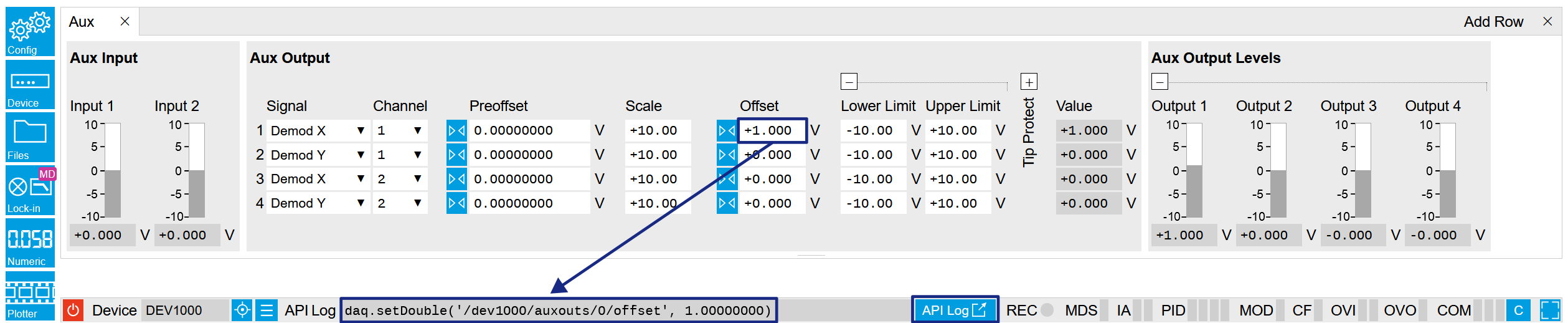
A convenient method to learn which node is responsible for a specific instrument setting is to check the Command Log history in the bottom of the LabOne User Interface. The command in the Status Bar gets updated every time a configuration change is made. Figure 1 shows how the equivalent MATLAB command is displayed after modifying the value of the auxiliary output 1’s offset. The format of the LabOne UI’s command history can be configured in the Config Tab (MATLAB, Python and .NET are available). The entire history generated in the current UI session can be viewed by clicking the "Show Log" button.

Figure 1: When a device’s configuration is modified in the LabOne User Interface, the Status Bar displays the equivalent command to perform the same configuration via a LabOne programming interface. Here, the MATLAB code to modify auxiliary output 1’s offset value is provided. When "Show Log" is clicked the entire configuration history is displayed in a new browser tab.

In a LabOne Programming Interface

A list of nodes (under a specific branch) can be requested from the Data Server in an API client using the listNodes command (MATLAB, Python, .NET) or ziAPIListNodes() function (C API). Please see each API’s command reference for more help using the listNodes command. To obtain a list of all the nodes that provide data from an instrument at a high rate, so-called streaming nodes, the streamingonly flag can be provided to listNodes. More information on data streaming and streaming nodes is available in the LabOne Programming Manual.

The detailed descriptions of nodes that is provided in Reference Node Documentation is accessible directly in the LabOne MATLAB or Python programming interfaces using the "help" command. The help command is daq.help(path) in Python and ziDAQ('help', path) in MATLAB. The command returns a description of the instrument node including access properties, data type, units and available options. The "help" command also handles wildcards to return a detailed description of all nodes matching the path. An example is provided below.

    daq = zhinst.core.ziDAQServer('localhost', 8004, 6)
    daq.help('/dev2006/auxouts/0/offset')
    # Out:
    # /dev1000/auxouts/0/offset#
    # Add the specified offset voltage to the signal after scaling. Auxiliary Output
    # Value = (Signal+Preoffset)*Scale + Offset
    # Properties: Read, Write, Setting
    # Type: Double
    # Unit: V

Data Server Nodes

The Data Server has nodes in the node tree available under the top-level /ZI/ branch. These nodes give information about the version and state of the Data Server the client is connected to. For example, the nodes:

  • /ZI/ABOUT/VERSION
  • /ZI/ABOUT/REVISION

are read-only nodes that contain information about the release version and revision of the Data Server. The nodes under the /ZI/DEVICES/ list which devices are connected, discoverable and visible to the Data Server.

The nodes:

  • /ZI/CONFIG/OPEN
  • /ZI/CONFIG/PORT

are settings nodes that can be used to configure which port the Data Server listens to for incoming client connections and whether it may accept connections from clients on hosts other than the localhost.

Nodes that are of particular use to programmers are:

  • /ZI/DEBUG/LOGPATH - the location of the Data Server’s log in the PC’s file system,
  • /ZI/DEBUG/LEVEL - the current log-level of the Data Server (configurable; has the Write attribute),
  • /ZI/DEBUG/LOG - the last Data Server log entries as a string array.

The Global nodes of the LabOne Data Server are listed in the Instrument Communication chapter of the LabOne Programming Manual

Reference Node Documentation

This section describes all the nodes in the data server’s node tree organized by branch.

AUXINS

/dev..../auxins/n/averaging

Properties: Read, Write, Setting
Type: Integer (64 bit)
Unit: None

Defines the number of samples on the input to average as a power of two. Possible values are in the range [0, 16]. A value of 0 corresponds to the sampling rate of the auxiliary input's ADC.

/dev..../auxins/n/sample

Properties: Read, Stream
Type: ZIAuxInSample
Unit: V

Voltage measured at the Auxiliary Input after averaging. The data rate depends on the averaging value. Note, if the instrument has demodulator functionality, the auxiliary input values are available as fields in a demodulator sample and are aligned by timestamp with the demodulator output.

/dev..../auxins/n/values/n

Properties: Read
Type: Double
Unit: V

Voltage measured at the Auxiliary Input after averaging. The value of this node is updated at a low rate (50 Hz); the streaming node auxins/n/sample is updated at a high rate defined by the averaging.

AUXOUTS

/dev..../auxouts/n/demodselect

Properties: Read, Write, Setting
Type: Integer (64 bit)
Unit: None

Select the channel number of the selected signal source.

/dev..../auxouts/n/limitlower

Properties: Read, Write, Setting
Type: Double
Unit: V

Lower limit for the signal at the Auxiliary Output. A smaller value will be clipped.

/dev..../auxouts/n/limitupper

Properties: Read, Write, Setting
Type: Double
Unit: V

Upper limit for the signal at the Auxiliary Output. A larger value will be clipped.

/dev..../auxouts/n/offset

Properties: Read, Write, Setting
Type: Double
Unit: V

Add the specified offset voltage to the signal after scaling. Auxiliary Output Value = (Signal+Preoffset)*Scale + Offset

/dev..../auxouts/n/outputselect

Properties: Read, Write, Setting
Type: Integer (enumerated)
Unit: None

Select the signal source to be represented on the Auxiliary Output.

-1 "manual": Select Manual as the output option.
0 "demod_x": Select Demod X as the output option.
1 "demod_y": Select Demod Y as the output option.
2 "demod_r": Select Demod R as the output option.
3 "demod_theta": Select Demod Theta as the output option.
5 "pid": Select PID Out as the output option.
9 "pid_shift": Select PID Shift as the output option.
10 "pid_error": Select PID Error as the output option.
11 "tu_filtered": Select TU Filtered Value as the output option.
13 "tu_output": Select TU Output Value as the output option.
/dev..../auxouts/n/preoffset

Properties: Read, Write, Setting
Type: Double
Unit: Dependent

Add a pre-offset to the signal before scaling is applied. Auxiliary Output Value = (Signal+Preoffset)*Scale + Offset

/dev..../auxouts/n/scale

Properties: Read, Write, Setting
Type: Double
Unit: None

Multiplication factor to scale the signal. Auxiliary Output Value = (Signal+Preoffset)*Scale + Offset

/dev..../auxouts/n/tipprotect/enable

Properties: Read, Write, Setting
Type: Integer (enumerated)
Unit: None

Enable the Tip Protect unit.

0 "off": Switch off the Tip Protect unit.
1 "on": Switch on the Tip Protect unit.
/dev..../auxouts/n/tipprotect/polarity

Properties: Read, Write, Setting
Type: Integer (enumerated)
Unit: None

Select the active level of Source signal.

0 "low": Active when the source signal is at low level.
1 "high": Active when the source signal is at high level.
/dev..../auxouts/n/tipprotect/source

Properties: Read, Write, Setting
Type: Integer (enumerated)
Unit: None

Select the input source for Tip Protect.

0 "tu_output0": Select Threshold Unit 1 as the source signal.
1 "tu_output1": Select Threshold Unit 2 as the source signal.
2 "tu_output2": Select Threshold Unit 3 as the source signal.
3 "tu_output3": Select Threshold Unit 4 as the source signal.
/dev..../auxouts/n/tipprotect/value

Properties: Read, Write, Setting
Type: Double
Unit: V

Signal value written to the Aux Output port when Tip Protect is active. The value overwrites Aux Output Internal value and the Lower and Upper Limits.

/dev..../auxouts/n/value

Properties: Read
Type: Double
Unit: V

Voltage present on the Auxiliary Output. Auxiliary Output Value = (Signal+Preoffset)*Scale + Offset

CLOCKBASE

/dev..../clockbase

Properties: Read
Type: Double
Unit: Hz

Returns the internal clock frequency of the device.

CURRINS

/dev..../currins/n/autorange

Properties: Read, Write
Type: Integer (64 bit)
Unit: None

Automatic adjustment of the Range to about two times the maximum current input amplitude measured over about 100 ms.

/dev..../currins/n/float

Properties: Read, Write, Setting
Type: Integer (enumerated)
Unit: None

Switches the input between floating (ON) and connected grounds (OFF). This setting applies both to the voltage and the current input. It is recommended to discharge the test device before connecting or to enable this setting only after the signal source has been connected to the Signal Input in grounded mode.

0 "off": OFF: GND connected
1 "on": ON: Floating
/dev..../currins/n/max

Properties: Read, Write
Type: Double
Unit: None

Gives the maximum measured input current (peak value) normalized to input range.

/dev..../currins/n/min

Properties: Read, Write
Type: Double
Unit: None

Gives the minimum measured input current (peak value) normalized to input range.

/dev..../currins/n/on

Properties: Read, Write, Setting
Type: Integer (64 bit)
Unit: None

Enables the current input.

/dev..../currins/n/range

Properties: Read, Write, Setting
Type: Double
Unit: A

Defines the gain of the current input amplifier. The range should exceed the incoming signal by roughly a factor of two including a potential DC offset. The instrument selects the next higher available range relative to a value inserted by the user. A suitable choice of this setting optimizes the accuracy and signal-to-noise ratio by ensuring that the full dynamic range of the input ADC is used.

/dev..../currins/n/rangestep/trigger

Properties: Read, Write
Type: Integer (64 bit)
Unit: None

Switches to the next appropriate input range such that the range fits best with the measured input current.

/dev..../currins/n/scaling

Properties: Read, Write, Setting
Type: Double
Unit: None

Applies the given scale factor to the current input.

DEMODS

/dev..../demods/n/adcselect

Properties: Read, Write, Setting
Type: Integer (enumerated)
Unit: None

Selects the input signal for the demodulator.

0 "sigin0", "signal_input0": Sig In 1
1 "currin0", "current_input0": Curr In 1
2 "trigin0", "trigger_input0": Trigger Input 1
3 "trigin1", "trigger_input1": Trigger Input 2
4 "auxout0", "auxiliary_output0": Aux Out 1
5 "auxout1", "auxiliary_output1": Aux Out 2
6 "auxout2", "auxiliary_output2": Aux Out 3
7 "auxout3", "auxiliary_output3": Aux Out 4
8 "auxin0", "auxiliary_input0": Aux In 1
9 "auxin1", "auxiliary_input1": Aux In 2
174 "demod_constant_input": Demodulate a constant input. This results in a sine wave of the frequency specified by the demodulator's oscillator with an amplitude of 1 (at lower frequencies; higher frequencies will be attenuated). The maximum possible frequency is limited by the demodulator sampling rate and bandwidth; use demodulator order 1 for the least attenuation in demodulator output. This signal may be used with the auxiliary outputs, PID and Threshold Unit for advanced measurement and control tasks. When the demodulator output is written to an auxiliary output, the resulting signal can also be used as a second output channel (for low frequencies).
/dev..../demods/n/enable

Properties: Read, Write, Setting
Type: Integer (enumerated)
Unit: None

Enables the data acquisition for the corresponding demodulator. Note: increasing number of active demodulators increases load on the physical connection to the host computer.

0 "off": OFF: demodulator inactive
1 "on": ON: demodulator active
/dev..../demods/n/freq

Properties: Read
Type: Double
Unit: Hz

Indicates the frequency used for demodulation and for output generation. The demodulation frequency is calculated with oscillator frequency times the harmonic factor. When the MOD option is used linear combinations of oscillator frequencies including the harmonic factors define the demodulation frequencies.

/dev..../demods/n/harmonic

Properties: Read, Write, Setting
Type: Integer (64 bit)
Unit: None

Multiplies the demodulator's reference frequency by an integer factor. If the demodulator is used as a phase detector in external reference mode (PLL), the effect is that the internal oscillator locks to the external frequency divided by the integer factor.

/dev..../demods/n/order

Properties: Read, Write, Setting
Type: Integer (enumerated)
Unit: None

Selects the filter roll off between 6 dB/oct and 48 dB/oct.

1 1st order filter 6 dB/oct
2 2nd order filter 12 dB/oct
3 3rd order filter 18 dB/oct
4 4th order filter 24 dB/oct
5 5th order filter 30 dB/oct
6 6th order filter 36 dB/oct
7 7th order filter 42 dB/oct
8 8th order filter 48 dB/oct
/dev..../demods/n/oscselect

Properties: Read, Write, Setting
Type: Integer (enumerated)
Unit: None

Connects the demodulator with the supplied oscillator. Number of available oscillators depends on the installed options.

0 Oscillator 1
1 Oscillator 2
2 Oscillator 3
3 Oscillator 4
/dev..../demods/n/phaseadjust

Properties: Read, Write
Type: Integer (64 bit)
Unit: None

Adjust the demodulator phase automatically in order to read 0 degrees.

/dev..../demods/n/phaseshift

Properties: Read, Write, Setting
Type: Double
Unit: deg

Phase shift applied to the reference input of the demodulator.

/dev..../demods/n/rate

Properties: Read, Write, Setting
Type: Double
Unit: 1/s

Defines the demodulator sampling rate, the number of samples that are sent to the host computer per second. A rate of about 7-10 higher as compared to the filter bandwidth usually provides sufficient aliasing suppression. This is also the rate of data received by LabOne Data Server and saved to the computer hard disk. This setting has no impact on the sample rate on the auxiliary outputs connectors. Note: the value inserted by the user may be approximated to the nearest value supported by the instrument.

/dev..../demods/n/sample

Properties: Read, Stream
Type: ZIDemodSample
Unit: Dependent

Contains streamed demodulator samples with sample interval defined by the demodulator data rate.

/dev..../demods/n/sinc

Properties: Read, Write, Setting
Type: Integer (64 bit)
Unit: None

Enables the sinc filter. When the filter bandwidth is comparable to or larger than the demodulation frequency, the demodulator output may contain frequency components at the frequency of demodulation and its higher harmonics. The sinc is an additional filter that attenuates these unwanted components in the demodulator output.

/dev..../demods/n/timeconstant

Properties: Read, Write, Setting
Type: Double
Unit: s

Sets the integration time constant or in other words, the cutoff frequency of the demodulator low pass filter.

/dev..../demods/n/trigger

Properties: Read, Write, Setting
Type: Integer (enumerated)
Unit: None

Selects the acquisition mode (i.e. triggering) of the demodulator.

0 "continuous": Continuous: demodulator data is continuously streamed to the host computer.
1 "trigin0_rising", "trigger_input0_rising": Trigger Input 1: rising edge triggered.
2 "trigin0_falling", "trigger_input0_falling": Trigger Input 1: falling edge triggered.
3 "trigin0_both", "trigger_input0_both": Trigger Input 1: triggering on both rising and falling edge.
4 "trigin1_rising", "trigger_input1_rising": Trigger Input 2: rising edge triggered.
5 "trigin0or1_rising", "trigger_input0or1_rising": Trigger Input 1 or 2: rising edge triggered on either input.
8 "trigin1_falling", "trigger_input1_falling": Trigger Input 2: falling edge triggered.
10 "trigin0or1_falling", "trigger_input0or1_falling": Trigger Input 1 or 2: falling edge triggered on either input.
12 "trigin1_both", "trigger_input1_both": Trigger Input 2: triggering on both rising and falling edge.
15 "trigin0or1_both", "trigger_input0or1_both": Trigger Input 1 or 2: triggering on both rising and falling edge or either trigger input.
16 "trigin0_low", "trigger_input0_low": Trigger Input 1: demodulator data is streamed to the host computer when the level is low (TTL).
32 "trigin0_high", "trigger_input0_high": Trigger Input 1 for MF: demodulator data is streamed to the host computer when the level is high (TTL).
64 "trigin1_low", "trigger_input1_low": Trigger Input 2: demodulator data is streamed to the host computer when the level is low (TTL).
80 "trigin0or1_low", "trigger_input0or1_low": Trigger Input 1 or 2: demodulator data is streamed to the host computer when either level is low (TTL).
128 "trigin1_high", "trigger_input1_high": Trigger Input 2: demodulator data is streamed to the host computer when the level is high (TTL).
160 "trigin0or1_high", "trigger_input0or1_high": Trigger Input 1 or 2: demodulator data is streamed to the host computer when either level is high (TTL).

DIOS

/dev..../dios/n/auxdrive

Properties: Read
Type: Integer (64 bit)
Unit: None

Not used. Reserved for future use.

/dev..../dios/n/decimation

Properties: Read, Write, Setting
Type: Integer (64 bit)
Unit: None

Sets the decimation factor for DIO data streamed to the host computer.

/dev..../dios/n/drive

Properties: Read, Write, Setting
Type: Integer (64 bit)
Unit: None

When on (1), the corresponding 8-bit bus is in output mode. When off (0), it is in input mode. Bit 0 corresponds to the least significant byte. For example, the value 1 drives the least significant byte, the value 8 drives the most significant byte.

/dev..../dios/n/extclk

Properties: Read, Write, Setting
Type: Integer (enumerated)
Unit: None

Select DIO internal or external clocking.

0 "internal": The DIO is internally clocked with a fixed frequency of 60 MHz.
1 "external": The DIO is externally clocked with a clock signal connected to DIO Pin 68. The available range is from 1 Hz up to the internal clock frequency.
/dev..../dios/n/input

Properties: Read, Stream
Type: ZIDIOSample
Unit: None

Gives the value of the DIO input for those bytes where drive is disabled.

/dev..../dios/n/mode

Properties: Read, Write, Setting
Type: Integer (enumerated)
Unit: None

Select DIO mode

0 "manual": Enables manual control of the DIO output bits.
3 "threshold_unit": Enables setting of DIO output values by the threshold unit.
/dev..../dios/n/output

Properties: Read, Write, Setting
Type: Integer (64 bit)
Unit: None

Sets the value of the DIO output for those bytes where 'drive' is enabled.

EXTREFS

/dev..../extrefs/n/adcselect

Properties: Read
Type: Integer (enumerated)
Unit: None

Indicates the input signal selection for the selected demodulator.

0 "sigin0", "signal_input0": Signal Input 1 is connected to the corresponding demodulator.
1 "currin0", "current_input0": Current Input 1 is connected to the corresponding demodulator.
2 "trigin0", "trigger_input0": Trigger Input 1 is connected to the corresponding demodulator.
3 "trigin1", "trigger_input1": Trigger Input 2 is connected to the corresponding demodulator.
4 "auxout0", "auxiliary_output0": Auxiliary Output 1 is connected to the corresponding demodulator.
5 "auxout1", "auxiliary_output1": Auxiliary Output 2 is connected to the corresponding demodulator.
6 "auxout2", "auxiliary_output2": Auxiliary Output 3 is connected to the corresponding demodulator.
7 "auxout3", "auxiliary_output3": Auxiliary Output 4 is connected to the corresponding demodulator.
8 "auxin0", "auxiliary_input0": Auxiliary Input 1 is connected to the corresponding demodulator.
9 "auxin1", "auxiliary_input1": Auxiliary Input 2 is connected to the corresponding demodulator.
/dev..../extrefs/n/automode

Properties: Read, Write, Setting
Type: Integer (enumerated)
Unit: None

This defines the type of automatic adaptation of parameters in the PID used for Ext Ref.

2 "low_bandwidth", "pid_coeffs_filter_low_bw": The PID coefficients, the filter bandwidth and the output limits are automatically set using a low bandwidth.
3 "high_bandwidth", "pid_coeffs_filter_high_bw": The PID coefficients, the filter bandwidth and the output limits are automatically set using a high bandwidth.
4 "all", "pid_coeffs_filter_auto_bw": The PID coefficient, the filter bandwidth and the output limits are dynamically adapted.
/dev..../extrefs/n/demodselect

Properties: Read, Write, Setting
Type: Integer (64 bit)
Unit: None

Indicates the demodulator connected to the extref channel.

/dev..../extrefs/n/enable

Properties: Read, Write, Setting
Type: Integer (64 bit)
Unit: None

Enables the external reference.

/dev..../extrefs/n/locked

Properties: Read
Type: Integer (64 bit)
Unit: None

Indicates whether the external reference is locked.

/dev..../extrefs/n/oscselect

Properties: Read
Type: Integer (64 bit)
Unit: None

Indicates which oscillator is being locked to the external reference.

FEATURES

/dev..../features/code

Properties: Write
Type: String
Unit: None

Node providing a mechanism to write feature codes.

/dev..../features/devtype

Properties: Read
Type: String
Unit: None

Returns the device type.

/dev..../features/options

Properties: Read
Type: String
Unit: None

Returns enabled options.

/dev..../features/serial

Properties: Read
Type: String
Unit: None

Device serial number.

IMPS

/dev..../imps/n/ac

Properties: Read, Write, Setting
Type: Integer (64 bit)
Unit: None

Defines the input coupling for the Signal Inputs. AC coupling inserts a high-pass filter.

/dev..../imps/n/auto/bw

Properties: Read, Write, Setting
Type: Integer (64 bit)
Unit: None

Enable automatic bandwidth control. If enabled the optimum bandwidth is calculated based on the frequency and measurement data.

/dev..../imps/n/auto/inputrange

Properties: Read, Write, Setting
Type: Integer (enumerated)
Unit: None

Select input range control mode.

0 Manual: In manual mode the current and voltage input ranges are adjusted manually and separately. Use this mode with care as overload will result in inaccurate impedance results.
1 Auto: Dynamically adjust the input range according to the measured input signal strength. This optimizes the dynamic range and precision of impedance measurements.
2 Zone: This ranging option allows you to manually set the switching frequency limits for all eight current input ranges.
/dev..../imps/n/auto/output

Properties: Read, Write, Setting
Type: Integer (64 bit)
Unit: None

If enabled, the drive voltage amplitude is controlled by the device. If disabled it can be set manually.

/dev..../imps/n/auto/suppress

Properties: Read, Write
Type: Integer (64 bit)
Unit: None

Indicates disabled periodic auto range control. A running sweeper module takes over the range control and thus disables the periodic range checks.

/dev..../imps/n/bias/enable

Properties: Read, Write, Setting
Type: Integer (64 bit)
Unit: None

Enables the DC bias voltage.

/dev..../imps/n/bias/value

Properties: Read, Write, Setting
Type: Double
Unit: V

DC bias voltage applied across the device under test. Both positive and negative bias voltages are supported. In a 4-terminal measurement, the bias voltage is limited by the maximum common voltage input range of the device. In a 2-terminal measurement, the bias voltage can be larger because the voltage inputs are not connected.

/dev..../imps/n/calib/internal/active

Properties: Read
Type: Integer (64 bit)
Unit: None

Indicates if the internal calibration is applied to the measurement data.

/dev..../imps/n/calib/internal/enable

Properties: Read, Write, Setting
Type: Integer (64 bit)
Unit: None

Enables the internal calibration. This ensures that the input range gains match over the full frequency range. With enabled internal calibration the device fulfills the impedance accuracy specification. The internal calibration is a prerequisite to apply a user compensation.

/dev..../imps/n/calib/internal/smooth

Properties: Read, Write, Setting
Type: Integer (64 bit)
Unit: None

Enables smoothing of the internal calibration data. This results in lower noise in the measured data.

/dev..../imps/n/calib/user/active

Properties: Read
Type: Integer (64 bit)
Unit: None

Indicates that a valid user compensation is active. If active the impedance data streams deliver amplitude and phase corrected data based on the impedance user compensation.

/dev..../imps/n/calib/user/enable

Properties: Read, Write, Setting
Type: Integer (64 bit)
Unit: None

Enables the user compensation of the impedance data. The user compensation is correcting parasitics and delays caused by the external setup. The user compensation is applied on top of the internal impedance calibration.

/dev..../imps/n/calib/user/smooth

Properties: Read, Write, Setting
Type: Integer (64 bit)
Unit: None

Enables smoothing of the compensation data. This results in lower noise in the measured data.

/dev..../imps/n/confidence/compensation/enable

Properties: Read, Write, Setting
Type: Integer (64 bit)
Unit: None

Enables the indication of strong compensation in the plots. A strong compensation diminishes the measurement accuracy of the parameter.

/dev..../imps/n/confidence/compensation/ratio

Properties: Read, Write, Setting
Type: Double
Unit: None

Strength of the compensation that will trigger the strong compensation warning.

/dev..../imps/n/confidence/enable

Properties: Read, Write, Setting
Type: Integer (64 bit)
Unit: None

Enables/disables all confidence indicators to check the reliability of the measured data. To enable individual indicators, open the advanced tab.

/dev..../imps/n/confidence/freqlimit/enable

Properties: Read, Write, Setting
Type: Integer (64 bit)
Unit: None

Enables the frequency limit detection based on the used current input range. Only relevant when Range Control is set to Manual.

/dev..../imps/n/confidence/lowdut2t/enable

Properties: Read, Write, Setting
Type: Integer (64 bit)
Unit: None

Enables a warning when meassuring a low impedance (100k) with a 2 point contact.

/dev..../imps/n/confidence/lowdut2t/ratio

Properties: Read, Write, Setting
Type: Double
Unit: None

When measuring with 2 point contacts, too low impedance of DUT will trigger the Low DUT 2T warning.

/dev..../imps/n/confidence/oneperiod/enable

Properties: Read, Write, Setting
Type: Integer (64 bit)
Unit: None

Enables the detection of unreliable data points where data sample loss leads to an invalid one-period average. Try reducing the data transfer rate.

/dev..../imps/n/confidence/opendetect/enable

Properties: Read, Write, Setting
Type: Integer (64 bit)
Unit: None

Enables the open terminal detection for 4-terminal measurements.

/dev..../imps/n/confidence/opendetect/ratio

Properties: Read, Write, Setting
Type: Double
Unit: None

Open terminal detection ratio. An open terminal is reported if the excitation calculated from current and voltage drop differs more than the specified factor from the driving voltage.

/dev..../imps/n/confidence/overflow/enable

Properties: Read, Write, Setting
Type: Integer (64 bit)
Unit: None

Enables the overload detection for current and voltage.

/dev..../imps/n/confidence/qfactor/enable

Properties: Read, Write, Setting
Type: Integer (64 bit)
Unit: None

Enables the detection of negative Q or D factors. Negative Q or D factors mean the measured impedance does not correspond to the chosen Representation. This can be due to an erroneous compensation, a bad choice of the Representation, or noise.

/dev..../imps/n/confidence/suppression/enable

Properties: Read, Write, Setting
Type: Integer (64 bit)
Unit: None

The Suppression Confidence Indicator indicates if one of the two parameters of a circuit representation cannot be calculated reliably from the measured impedance. This is the case if a small variation in one (dominant) representation parameter creates a strong variation of the other (suppressed) representation parameter. Such an error amplification indicates that the measurement of the secondary parameter is unreliable.

/dev..../imps/n/confidence/suppression/ratio

Properties: Read, Write, Setting
Type: Double
Unit: None

Error amplification limit for which a secondary parameter is marked unreliable. Larger gain values mean larger warning tolerances. A gain value between 10 and 100 is best.

/dev..../imps/n/confidence/underflow/enable

Properties: Read, Write, Setting
Type: Integer (64 bit)
Unit: None

Enables the underflow detection for current and voltage.

/dev..../imps/n/confidence/underflow/ratio

Properties: Read, Write, Setting
Type: Double
Unit: None

The underflow condition is met if the measured amplitude is lower than the specified ratio relative to full scale.

/dev..../imps/n/current/demodselect

Properties: Read
Type: Integer (64 bit)
Unit: None

Demodulator used for current demodulation.

/dev..../imps/n/current/inputselect

Properties: Read, Write, Setting
Type: Integer (enumerated)
Unit: None

Select the current input used for two- and four-terminal impedance measurements.

0 "currin0", "current_input0": Current Input 1
8 "auxin0", "auxiliary_input0": Aux In 1
9 "auxin1", "auxiliary_input1": Aux In 2
/dev..../imps/n/current/invert

Properties: Read, Write, Setting
Type: Integer (64 bit)
Unit: None

If enabled, the current input signal is inverted. This is useful to switch the polarity of an input signal which can be caused by additional current amplifiers.

/dev..../imps/n/current/pid/enable

Properties: Read, Write, Setting
Type: Integer (64 bit)
Unit: None

If enabled, the PID value is used for the impedance calculation instead of the measured value at the current input.

/dev..../imps/n/current/range

Properties: Read, Write, Setting
Type: Double
Unit: A

Input current range used for the impedance measurement. Small current input ranges have a reduced bandwidth. In the Range Control modes 'Auto' and 'Impedance', the current range is switched automatically to a higher range if the frequency is too high.

/dev..../imps/n/current/scaling

Properties: Read, Write, Setting
Type: Double
Unit: A/V

The scaling factor will be applied to the current measurement done with an Aux In input.

/dev..../imps/n/demod/harmonic

Properties: Read, Write, Setting
Type: Integer (64 bit)
Unit: None

Multiplies the demodulator's reference frequency with the integer factor defined by this field.

/dev..../imps/n/demod/order

Properties: Read, Write, Setting
Type: Integer (enumerated)
Unit: None

Selects the filter roll off between 6 dB/oct and 48 dB/oct of the current demodulator.

1 1st order filter 6 dB/oct
2 2nd order filter 12 dB/oct
3 3rd order filter 18 dB/oct
4 4th order filter 24 dB/oct
5 5th order filter 30 dB/oct
6 6th order filter 36 dB/oct
7 7th order filter 42 dB/oct
8 8th order filter 48 dB/oct
/dev..../imps/n/demod/oscselect

Properties: Read, Write, Setting
Type: Integer (enumerated)
Unit: None

Oscillator used to generate the frequency of the excitation voltage on the Hcur (+V) connector.

0 Oscillator 1
1 Oscillator 2
2 Oscillator 3
3 Oscillator 4
/dev..../imps/n/demod/rate

Properties: Read, Write, Setting
Type: Double
Unit: 1/s

Impedance data streaming rate. The same data rate is applied to the demodulators that are used for the impedance measurement.

/dev..../imps/n/demod/sinc

Properties: Read, Write, Setting
Type: Integer (64 bit)
Unit: None

Enables the sinc filter.

/dev..../imps/n/demod/timeconstant

Properties: Read, Write, Setting
Type: Double
Unit: s

Defines low pass filter time constant.

/dev..../imps/n/discard/enable

Properties: Read, Write, Setting
Type: Integer (64 bit)
Unit: None

Discarding impedance samples outside the indicated range.

/dev..../imps/n/discard/limitlower

Properties: Read, Write, Setting
Type: Double
Unit: None

Threshold for abs(Z) below which the impedance samples are discarded.

/dev..../imps/n/discard/limitupper

Properties: Read, Write, Setting
Type: Double
Unit: None

Threshold for abs(Z) above which the impedance samples are discarded.

/dev..../imps/n/enable

Properties: Read, Write, Setting
Type: Integer (64 bit)
Unit: None

Enable impedance calculation for demodulator data.

/dev..../imps/n/freq

Properties: Read, Write, Setting
Type: Double
Unit: Hz

Frequency control for the oscillator used for impedance measurement.

/dev..../imps/n/interpolation

Properties: Read, Write, Setting
Type: Integer (enumerated)
Unit: None

Select the interpolation method of the compensation data. The interpolation method is particularly important if the derivative changes strongly e.g at cut-off frequencies.

0 "linear": Linear: The linear interpolation is fastest but may create compensation errors in between the frequency points used for compensation.
1 "pchip": Piecewise Cubic Hermite (PCHIP): The piecewise cubic Hermite interpolation will result in very accurate results but requires more calculation power.
/dev..../imps/n/maxbandwidth

Properties: Read, Write, Setting
Type: Double
Unit: Hz

Limit of the maximum bandwidth used on the demodulator filter. Values above 1 kHz can heavily diminish measurement accuracy in the high-frequency region where the amplitude is no more constant over frequency.

/dev..../imps/n/mode

Properties: Read, Write, Setting
Type: Integer (enumerated)
Unit: None

Select impedance measurement mode.

0 4 Terminal: This method uses the current and the voltage drop across the DUT to calculate the DUT impedance. This method results in very accurate measurements as influences of series resistors on the output and current input are excluded.
1 2 Terminal: This method uses the driving voltage and the measured current to calculate the DUT impedance. The 2 Terminal method can be beneficial when measuring very high impedance where the parasitics of the voltage measurement are limiting the frequency range.
/dev..../imps/n/model

Properties: Read, Write, Setting
Type: Integer (enumerated)
Unit: None

Representation of the complex impedance value Z by two real values accessible as Parameter 1 and Parameter 2 on all user interface displays.

0 "r_c_parallel": Rp || Cp: Impedance value Z is represented by a resistive element Rp in parallel with a capacitive element Cp.
1 "r_c_series": Rs + Cs: Impedance value Z is represented by a resistive element Rs in series with a capacitive element Cs.
2 "r_l_series": Rs + Ls: Impedance value Z is represented by a resistive element Rs in series with an inductive element Ls.
3 "g_b_parallel", "admittance": G B: Impedance value Z is represented by conductance G = Real(Y) and Susceptance B = Imag(Y) of the admittance Y = 1/Z.
4 "d_c_series": D Cs: Impedance value Z is represented by a dissipation factor D = -Real(Z)/Imag(Z) (loss tangent) and a series capacitive element.
5 "q_c_series": Q Cs: Impedance value Z is represented by a quality factor Q = -Imag(Z)/Real(Z) and a series capacitive element.
6 "d_l_series": D Ls: Impedance value Z is represented by a dissipation factor D = Real(Z)/Imag(Z) (loss tangent) and a series inductive element.
7 "q_l_series": Q Ls: Impedance value Z is represented by a quality factor Q = Imag(Z)/Real(Z) and a series inductive element.
8 "r_l_parallel": Rp || Lp: Impedance value Z is represented by a resistive element Rp in parallel with an inductive element Lp.
9 "d_c_parallel": D Cp: Impedance value Z is represented by a dissipation factor D = Real(Z)/Imag(Z) (loss tangent) and a parallel capacitive element Cp.
10 "dielectric": Dielectic: Impedance value Z is represented by an equivalent dieletric material with a complex permittivity.
/dev..../imps/n/mut/area

Properties: Read, Write, Setting
Type: Double
Unit:

The area of the MUT. Only relevant when using the dielectric model.

/dev..../imps/n/mut/thickness

Properties: Read, Write, Setting
Type: Double
Unit: m

The thickness of the MUT. Only relevant when using the dielectric model.

/dev..../imps/n/omegasuppression

Properties: Read, Write, Setting
Type: Double
Unit: dB

Suppression of the omega and 2-omega components. Small omega suppression can diminish measurements of very low or high impedance because the DC component can become dominant. Large omega suppression will have a significant impact on sweep time especially for low filter orders.

/dev..../imps/n/oneperiod/active

Properties: Read, Write, Setting
Type: Integer (64 bit)
Unit: None

Enables one-period averaging for low frequency impedance measurements. The LED is green when active.

/dev..../imps/n/oneperiod/enable

Properties: Read, Write, Setting
Type: Integer (64 bit)
Unit: None

Enables one-period averaging for low frequency impedance measurements. The LED is green when active.

/dev..../imps/n/output/amplitude

Properties: Read, Write, Setting
Type: Double
Unit: V

Drive amplitude on the Signal Output.

/dev..../imps/n/output/demod

Properties: Read
Type: Integer (64 bit)
Unit: None

Demodulator unit used to generate the excitation voltage on the Signal Output.

/dev..../imps/n/output/on

Properties: Read, Write, Setting
Type: Integer (64 bit)
Unit: None

Main switch for the Signal Output corresponding to the blue LED indicator on the instrument front panel.

/dev..../imps/n/output/range

Properties: Read, Write, Setting
Type: Double
Unit: V

Selects the output voltage range.

/dev..../imps/n/output/select

Properties: Read
Type: Integer (enumerated)
Unit: None

Selects the output channel that the excitation voltage drives.

0 "sigout0", "signal_output0": Signal Output 1
/dev..../imps/n/sample

Properties: Read, Stream
Type: ZIImpedanceSample
Unit: None

Streaming node containing the impedance measurement sample data.

/dev..../imps/n/voltage/demodselect

Properties: Read
Type: Integer (64 bit)
Unit: None

Demodulator used for voltage measurement in case of a four-terminal impedance measurement.

/dev..../imps/n/voltage/inputselect

Properties: Read, Write, Setting
Type: Integer (enumerated)
Unit: None

Select the voltage input used for a four-terminal impedance measurement.

0 "voltage_input0": Voltage Input 1
8 "auxin0", "auxiliary_input0": Aux In 1
9 "auxin1", "auxiliary_input1": Aux In 2
/dev..../imps/n/voltage/invert

Properties: Read, Write, Setting
Type: Integer (64 bit)
Unit: None

If enabled, the voltage input signal is inverted.

/dev..../imps/n/voltage/range

Properties: Read, Write, Setting
Type: Double
Unit: V

Input voltage range for the impedance measurement.

/dev..../imps/n/voltage/scaling

Properties: Read, Write, Setting
Type: Double
Unit: V/V

The scaling factor will be applied to the voltage meaurement done with an Aux In input.

MODS

/dev..../mods/n/carrier/amplitude

Properties: Read, Write, Setting
Type: Double
Unit: V

Set the carrier amplitude

/dev..../mods/n/carrier/enable

Properties: Read, Write, Setting
Type: Integer (64 bit)
Unit: None

Enable the modulation

/dev..../mods/n/carrier/harmonic

Properties: Read, Write, Setting
Type: Integer (64 bit)
Unit: None

Set the harmonic of the carrier frequency. 1 = Fundamental

/dev..../mods/n/carrier/inputselect

Properties: Read, Write, Setting
Type: Integer (enumerated)
Unit: None

Select Signal Input for the carrier demodulation

0 "sigin0", "signal_input0": Sig In 1
1 "currin0", "current_input0": Curr In 1
2 "trigin0", "trigger_input0": Trigger Input 1
3 "trigin1", "trigger_input1": Trigger Input 2
4 "auxout0", "auxiliary_output0": Aux Out 1
5 "auxout1", "auxiliary_output1": Aux Out 2
6 "auxout2", "auxiliary_output2": Aux Out 3
7 "auxout3", "auxiliary_output3": Aux Out 4
8 "auxin0", "auxiliary_input0": Aux In 1
9 "auxin1", "auxiliary_input1": Aux In 2
174 "demod_constant_input": Demodulate a constant input. This results in a sine wave of the frequency specified by the demodulator's oscillator with an amplitude of 1 (at lower frequencies; higher frequencies will be attenuated). The maximum possible frequency is limited by the demodulator sampling rate and bandwidth; use demodulator order 1 for the least attenuation in demodulator output. This signal may be used with the auxiliary outputs, PID and Threshold Unit for advanced measurement and control tasks. When the demodulator output is written to an auxiliary output, the resulting signal can also be used as a second output channel (for low frequencies).
/dev..../mods/n/carrier/order

Properties: Read, Write, Setting
Type: Integer (enumerated)
Unit: None

Selects the filter roll off between 6 dB/oct and 48 dB/oct for carrier demodulation

1 1st order filter 6 dB/oct
2 2nd order filter 12 dB/oct
3 3rd order filter 18 dB/oct
4 4th order filter 24 dB/oct
5 5th order filter 30 dB/oct
6 6th order filter 36 dB/oct
7 7th order filter 42 dB/oct
8 8th order filter 48 dB/oct
/dev..../mods/n/carrier/oscselect

Properties: Read, Write, Setting
Type: Integer (enumerated)
Unit: None

Select the oscillator for the carrier signal.

0 Oscillator 1
1 Oscillator 2
2 Oscillator 3
3 Oscillator 4
/dev..../mods/n/carrier/phaseadjust

Properties: Read, Write
Type: Integer (64 bit)
Unit: None

Adjust the carrier demodulator phase automatically in order to read 0 degrees.

/dev..../mods/n/carrier/phaseshift

Properties: Read, Write, Setting
Type: Double
Unit: degree

Phase shift applied to the reference input of the carrier demodulator and also to the carrier signal on the Signal Outputs

/dev..../mods/n/carrier/timeconstant

Properties: Read, Write, Setting
Type: Double
Unit: s

Sets the integration time constant or in other words, the cutoff frequency of the low-pass filter for the carrier demodulation.

/dev..../mods/n/enable

Properties: Read, Write, Setting
Type: Integer (64 bit)
Unit: None

Enables the modulation.

/dev..../mods/n/freqdev

Properties: Read, Write, Setting
Type: Double
Unit: Hz

FM mode peak deviation value.

/dev..../mods/n/freqdevenable

Properties: Read, Write, Setting
Type: Integer (enumerated)
Unit: None

In FM mode, choose to work with either modulation index or peak deviation. The modulation index equals peak deviation divided by modulation frequency.

0 "modulation_index": Use modulation index.
1 "peak_deviation": Use peak deviation.
/dev..../mods/n/index

Properties: Read, Write, Setting
Type: Double
Unit: None

FM modulation index: The modulation index equals peak deviation divided by modulation frequency.

/dev..../mods/n/mode

Properties: Read, Write, Setting
Type: Integer (enumerated)
Unit: None

Select the modulation mode.

0 "am": AM Modulation
1 "fm": FM Modulation
2 "manual": Manual
/dev..../mods/n/output

Properties: Read, Write, Setting
Type: Integer (enumerated)
Unit: None

Select Signal Output.

0 "none": None
1 "sigout0", "signal_output0": Signal Output 1
/dev..../mods/n/sidebands/n/amplitude

Properties: Read, Write, Setting
Type: Double
Unit: V

Set the amplitude of the sideband components.

/dev..../mods/n/sidebands/n/enable

Properties: Read, Write, Setting
Type: Integer (64 bit)
Unit: None

Enable the signal generation for the respective sideband

/dev..../mods/n/sidebands/n/harmonic

Properties: Read, Write, Setting
Type: Integer (64 bit)
Unit: None

Set harmonic of the sideband frequencies. 1 = fundamental

/dev..../mods/n/sidebands/n/inputselect

Properties: Read, Write, Setting
Type: Integer (enumerated)
Unit: None

Select Signal Input for the sideband demodulation

0 "sigin0", "signal_input0": Sig In 1
1 "currin0", "current_input0": Curr In 1
2 "trigin0", "trigger_input0": Trigger Input 1
3 "trigin1", "trigger_input1": Trigger Input 2
4 "auxout0", "auxiliary_output0": Aux Out 1
5 "auxout1", "auxiliary_output1": Aux Out 2
6 "auxout2", "auxiliary_output2": Aux Out 3
7 "auxout3", "auxiliary_output3": Aux Out 4
8 "auxin0", "auxiliary_input0": Aux In 1
9 "auxin1", "auxiliary_input1": Aux In 2
174 "demod_constant_input": Demodulate a constant input. This results in a sine wave of the frequency specified by the demodulator's oscillator with an amplitude of 1 (at lower frequencies; higher frequencies will be attenuated). The maximum possible frequency is limited by the demodulator sampling rate and bandwidth; use demodulator order 1 for the least attenuation in demodulator output. This signal may be used with the auxiliary outputs, PID and Threshold Unit for advanced measurement and control tasks. When the demodulator output is written to an auxiliary output, the resulting signal can also be used as a second output channel (for low frequencies).
/dev..../mods/n/sidebands/n/mode

Properties: Read, Write, Setting
Type: Integer (enumerated)
Unit: None

Enabling of the first sideband and selection of the position of the sideband relative to the carrier frequency for manual mode.

0 "off": Off: First sideband is disabled. The sideband demodulator behaves like a normal demodulator.
1 "upper": C + M: First sideband to the right of the carrier
2 "lower": C - M: First sideband to the left of the carrier
/dev..../mods/n/sidebands/n/order

Properties: Read, Write, Setting
Type: Integer (enumerated)
Unit: None

Selects the filter roll off between 6 dB/oct and 48 dB/oct for sideband demodulation

1 1st order filter 6 dB/oct
2 2nd order filter 12 dB/oct
3 3rd order filter 18 dB/oct
4 4th order filter 24 dB/oct
5 5th order filter 30 dB/oct
6 6th order filter 36 dB/oct
7 7th order filter 42 dB/oct
8 8th order filter 48 dB/oct
/dev..../mods/n/sidebands/n/oscselect

Properties: Read, Write, Setting
Type: Integer (enumerated)
Unit: None

Select the oscillator for the second sideband.

0 Oscillator 1
1 Oscillator 2
2 Oscillator 3
3 Oscillator 4
/dev..../mods/n/sidebands/n/phaseadjust

Properties: Read, Write
Type: Integer (64 bit)
Unit: None

Adjust the sideband demodulator phase automatically in order to read 0 degrees.

/dev..../mods/n/sidebands/n/phaseshift

Properties: Read, Write, Setting
Type: Double
Unit: degree

Phase shift applied to the reference input of the sideband demodulator and also to the sideband signal on the Signal Outputs

/dev..../mods/n/sidebands/n/timeconstant

Properties: Read, Write, Setting
Type: Double
Unit: s

Sets the integration time constant or in other words, the cutoff frequency of the low-pass filter for the sideband demodulation.

OSCS

/dev..../oscs/n/freq

Properties: Read, Write, Setting
Type: Double
Unit: Hz

Frequency control for each oscillator.

PIDS

/dev..../pids/n/center

Properties: Read, Write, Setting
Type: Double
Unit: Dependent

Sets the center value for the PID output. After adding the Center value, the signal is clamped to Center + Lower Limit and Center + Upper Limit.

/dev..../pids/n/d

Properties: Read, Write, Setting
Type: Double
Unit: Dependent

PID derivative gain.

/dev..../pids/n/demod/adcselect

Properties: Read
Type: Integer (enumerated)
Unit: None

Indicates the signal source which is connected to the chosen input demodulator channel.

0 "sigin0", "signal_input0": Signal Input 1 is connected to the corresponding demodulator.
1 "currin0", "current_input0": Current Input 1 is connected to the corresponding demodulator.
2 "trigin0", "trigger_input0": Trigger Input 1 is connected to the corresponding demodulator.
3 "trigin1", "trigger_input1": Trigger Input 2 is connected to the corresponding demodulator.
4 "auxout0", "auxiliary_output0": Auxiliary Output 1 is connected to the corresponding demodulator.
5 "auxout1", "auxiliary_output1": Auxiliary Output 2 is connected to the corresponding demodulator.
6 "auxout2", "auxiliary_output2": Auxiliary Output 3 is connected to the corresponding demodulator.
7 "auxout3", "auxiliary_output3": Auxiliary Output 4 is connected to the corresponding demodulator.
8 "auxin0", "auxiliary_input0": Auxiliary Input 1 is connected to the corresponding demodulator.
9 "auxin1", "auxiliary_input1": Auxiliary Input 2 is connected to the corresponding demodulator.
/dev..../pids/n/demod/harmonic

Properties: Read, Write, Setting
Type: Integer (64 bit)
Unit: None

Multiplier of the for the reference frequency of the current demodulator.

/dev..../pids/n/demod/order

Properties: Read, Write, Setting
Type: Integer (enumerated)
Unit: None

Selects the filter roll off between 6 dB/oct and 48 dB/oct of the current demodulator.

1 1st order filter 6 dB/oct
2 2nd order filter 12 dB/oct
3 3rd order filter 18 dB/oct
4 4th order filter 24 dB/oct
5 5th order filter 30 dB/oct
6 6th order filter 36 dB/oct
7 7th order filter 42 dB/oct
8 8th order filter 48 dB/oct
/dev..../pids/n/demod/timeconstant

Properties: Read, Write, Setting
Type: Double
Unit: s

Defines the characteristic time constant (cut off) of the demodulator filter used as an input.

/dev..../pids/n/dlimittimeconstant

Properties: Read, Write, Setting
Type: Double
Unit: s

The cutoff of the low-pass filter for the D limitation given as time constant. When set to 0, the low-pass filter is disabled.

/dev..../pids/n/enable

Properties: Read, Write, Setting
Type: Integer (64 bit)
Unit: None

Enable the PID controller.

/dev..../pids/n/error

Properties: Read
Type: Double
Unit: Dependent

Error = Set point - PID Input.

/dev..../pids/n/i

Properties: Read, Write, Setting
Type: Double
Unit: Dependent

PID integral gain I.

/dev..../pids/n/input

Properties: Read, Write, Setting
Type: Integer (enumerated)
Unit: None

Select input source of PID controller.

0 "demod_x": Demodulator X
1 "demod_y": Demodulator Y
2 "demod_r": Demodulator R
3 "demod_theta": Demodulator Theta
4 "auxin", "auxiliary_input": Aux Input
5 "auxout", "auxiliary_output": Aux Output
/dev..../pids/n/inputchannel

Properties: Read, Write, Setting
Type: Integer (64 bit)
Unit: None

Select input channel of PID controller.

/dev..../pids/n/keepint

Properties: Read, Write, Setting
Type: Integer (64 bit)
Unit: Dependent

If enabled, the accumulated integral error is maintained upon restart of the PID. If is disabled, the integral error is set to zero when the PID is disabled.

/dev..../pids/n/limitlower

Properties: Read, Write, Setting
Type: Double
Unit: Dependent

Sets the lower limit for the PID output. After adding the Center value, the signal is clamped to Center + Lower Limit and Center + Upper Limit.

/dev..../pids/n/limitupper

Properties: Read, Write, Setting
Type: Double
Unit: Dependent

Sets the upper limit for the PID output. After adding the Center value, the signal is clamped to Center + Lower Limit and Center + Upper Limit.

/dev..../pids/n/mode

Properties: Read, Write, Setting
Type: Integer (enumerated)
Unit: None

Sets the operation mode of the PID module.

0 "pid": PID
1 "pll": PLL (phase locked loop)
2 "extref": ExtRef (external reference)
/dev..../pids/n/output

Properties: Read, Write, Setting
Type: Integer (enumerated)
Unit: None

Select output of the PID controller.

0 "sigout0_amp", "signal_output0_amplitude": Driving Signal Output 1 amplitudes
2 "oscillator_frequency": Controlling any of the internal oscillator frequencies
3 "demod_phase": Controlling any of the demodulator phase set points
5 "auxout_offset", "auxiliary_output_offset": Driving any of the 4 Auxiliary Outputs' offset
7 "sigout_offset", "signal_output_offset": Driving the main Signal Output's offset
/dev..../pids/n/outputchannel

Properties: Read, Write, Setting
Type: Integer (64 bit)
Unit: None

Select the output channel of the driven output of PID controller.

/dev..../pids/n/p

Properties: Read, Write, Setting
Type: Double
Unit: Dependent

PID Proportional gain P.

/dev..../pids/n/phaseunwrap

Properties: Read, Write, Setting
Type: Integer (64 bit)
Unit: None

Enables the phase unwrapping to track phase errors past the +/-180 degree boundary and increase PLL bandwidth.

/dev..../pids/n/pll/automode

Properties: Read, Write, Setting
Type: Integer (enumerated)
Unit: None

This defines the type of automatic adaptation of parameters in the PID.

0 "no_adaption": No automatic adaption.
1 "pid_coeffs": The PID coefficients are automatically set based on the filter parameters.
2 "pid_coeffs_filter_low_bw": The PID coefficients, the filter bandwidth and the output limits are automatically set using a low bandwidth.
3 "pid_coeffs_filter_high_bw": The PID coefficients, the filter bandwidth and the output limits are automatically set using a high bandwidth.
/dev..../pids/n/pll/locked

Properties: Read
Type: Integer (64 bit)
Unit: None

Indicates when the PID, configured as PLL, is locked.

/dev..../pids/n/rate

Properties: Read, Write, Setting
Type: Double
Unit: 1/s

PID sampling rate and update rate of PID outputs. Needs to be set substantially higher than the targeted loop filter bandwidth.

/dev..../pids/n/setpoint

Properties: Read, Write, Setting
Type: Double
Unit: Dependent

PID controller setpoint

/dev..../pids/n/setpointtoggle/enable

Properties: Read, Write, Setting
Type: Integer (64 bit)
Unit: None

Enables the setpoint toggle.

/dev..../pids/n/setpointtoggle/rate

Properties: Read, Write, Setting
Type: Double
Unit: Hz

Defines the rate of setpoint toggling. Note that possible values are logarithmically spaced with a factor of 4 between values.

/dev..../pids/n/setpointtoggle/setpoint

Properties: Read, Write, Setting
Type: Double
Unit: Dependent

Defines the setpoint value used for setpoint toggle.

/dev..../pids/n/shift

Properties: Read
Type: Double
Unit: Dependent

Difference between the current output value Out and the Center. Shift = PError + IInt(Error, dt) + D*dError/dt

/dev..../pids/n/stream/effectiverate

Properties: Read
Type: Double
Unit: 1/s

Current rate of the PID stream data sent to PC. Defined based on Max Rate.

/dev..../pids/n/stream/error

Properties: Read, Stream
Type: Double
Unit: Dependent

PID Error = Set point - PID Input.

/dev..../pids/n/stream/overflow

Properties: Read
Type: Integer (64 bit)
Unit: None

Indicates the streaming fifo overflow state. 0 = OK, 1 = overflow.

/dev..../pids/n/stream/rate

Properties: Read, Write, Setting
Type: Double
Unit: 1/s

Target Rate for PID output data sent to PC. This value defines the applied decimation for sending data to the PC. It does not affect any other place where PID data are used.

/dev..../pids/n/stream/shift

Properties: Read, Stream
Type: Double
Unit: Dependent

Gives the difference between the current output value and the center value. Shift = PError + IInt(Error, dt) + D*dError/dt

/dev..../pids/n/stream/value

Properties: Read, Stream
Type: Double
Unit: Dependent

Gives the current PID output value.

/dev..../pids/n/value

Properties: Read
Type: Double
Unit: Dependent

Gives the current PID output value.

SCOPES

/dev..../scopes/n/channel

Properties: Read, Write, Setting
Type: Integer (enumerated)
Unit: None

Activates the scope channels.

1 Only channel 1 is active.
2 Only channel 2 is active.
3 "both": Both, channel 1 and 2 are active.
/dev..../scopes/n/channels/n/bwlimit

Properties: Read, Write, Setting
Type: Integer (enumerated)
Unit: None

Selects between sample decimation and sample averaging. Averaging avoids aliasing, but may conceal signal peaks.

0 "on": On: Selects sample averaging for sample rates lower than the maximal available sampling rate.
1 "off": OFF: Selects sample decimation for sample rates lower than the maximal available sampling rate.
/dev..../scopes/n/channels/n/fullscale

Properties: Read, Write, Setting
Type: Double
Unit: Dependent

Indicates the full scale value of the scope channel.

/dev..../scopes/n/channels/n/inputselect

Properties: Read, Write, Setting
Type: Integer (enumerated)
Unit: None

Selects the scope input signal.

0 "sigin0", "signal_input0": Signal Input 1
1 "currin0", "current_input0": Current Input 1
2 "trigin0", "trigger_input0": Trigger Input 1
3 "trigin1", "trigger_input1": Trigger Input 2
4 "auxout0", "auxiliary_output0": Aux Output 1. Requires an installed digitizer (DIG) option.
5 "auxout1", "auxiliary_output1": Aux Output 2. Requires an installed digitizer (DIG) option.
6 "auxout2", "auxiliary_output2": Aux Output 3. Requires an installed digitizer (DIG) option.
7 "auxout3", "auxiliary_output3": Aux Output 4. Requires an installed digitizer (DIG) option.
8 "auxin0", "auxiliary_input0": Aux Input 1
9 "auxin1", "auxiliary_input1": Aux Input 2
10 "demod1": Osc φ Demod 2
11 "demod3": Osc φ Demod 4
14 "trigout0", "trigger_output0": Trigger Output 1
15 "trigout1", "trigger_output1": Trigger Output 2
16 "demod0_x": Demod 1 X. Requires an installed digitizer (DIG) option.
17 "demod1_x": Demod 2 X. Requires an installed digitizer (DIG) option.
18 "demod2_x": Demod 3 X. Requires an installed digitizer (DIG) option.
19 "demod3_x": Demod 4 X. Requires an installed digitizer (DIG) option.
32 "demod0_y": Demod 1 Y. Requires an installed digitizer (DIG) option.
33 "demod1_y": Demod 2 Y. Requires an installed digitizer (DIG) option.
34 "demod2_y": Demod 3 Y. Requires an installed digitizer (DIG) option.
35 "demod3_y": Demod 4 Y. Requires an installed digitizer (DIG) option.
48 "demod0_r": Demod 1 R. Requires an installed digitizer (DIG) option.
49 "demod1_r": Demod 2 R. Requires an installed digitizer (DIG) option.
50 "demod2_r": Demod 3 R. Requires an installed digitizer (DIG) option.
51 "demod3_r": Demod 4 R. Requires an installed digitizer (DIG) option.
64 "demod0_theta": Demod 1 Θ. Requires an installed digitizer (DIG) option.
65 "demod1_theta": Demod 2 Θ. Requires an installed digitizer (DIG) option.
66 "demod2_theta": Demod 3 Θ. Requires an installed digitizer (DIG) option.
67 "demod3_theta": Demod 4 Θ. Requires an installed digitizer (DIG) option.
80 "pid0_value": PID 1 value. Requires an installed digitizer (DIG) option.
81 "pid1_value": PID 2 value. Requires an installed digitizer (DIG) option.
82 "pid2_value": PID 3 value. Requires an installed digitizer (DIG) option.
83 "pid3_value": PID 4 value. Requires an installed digitizer (DIG) option.
144 "pid0_shift": PID 1 Shift. Requires an installed digitizer (DIG) option.
145 "pid1_shift": PID 2 Shift. Requires an installed digitizer (DIG) option.
146 "pid2_shift": PID 3 Shift. Requires an installed digitizer (DIG) option.
147 "pid3_shift": PID 4 Shift. Requires an installed digitizer (DIG) option.
160 Reserved for future use.
161 Reserved for future use.
208 "pid0_error": PID 1 Error. Requires an installed digitizer (DIG) option.
209 "pid1_error": PID 2 Error. Requires an installed digitizer (DIG) option.
210 "pid2_error": PID 3 Error. Requires an installed digitizer (DIG) option.
211 "pid3_error": PID 4 Error. Requires an installed digitizer (DIG) option.
240 Reserved for future use.
241 Reserved for future use.
242 Reserved for future use.
243 Reserved for future use.
/dev..../scopes/n/channels/n/limitlower

Properties: Read, Write, Setting
Type: Double
Unit: Dependent

Lower limit of the scope full scale range. For demodulator, PID, Boxcar, and AU signals the limit should be adjusted so that the signal covers the specified range to achieve optimal resolution.

/dev..../scopes/n/channels/n/limitupper

Properties: Read, Write, Setting
Type: Double
Unit: Dependent

Upper limit of the scope full scale range. For demodulator, PID, Boxcar, and AU signals the limit should be adjusted so that the signal covers the specified range to achieve optimal resolution.

/dev..../scopes/n/channels/n/offset

Properties: Read, Write, Setting
Type: Double
Unit: Dependent

Indicates the offset value of the scope channel.

/dev..../scopes/n/enable

Properties: Read, Write, Setting
Type: Integer (64 bit)
Unit: None

Enables the acquisition of scope shots.

/dev..../scopes/n/length

Properties: Read, Write, Setting
Type: Integer (64 bit)
Unit: None

Defines the length of the recorded Scope shot in number of samples.

/dev..../scopes/n/segments/count

Properties: Read, Write, Setting
Type: Integer (64 bit)
Unit: None

Specifies the number of segments to be recorded in device memory. The maximum scope shot size is given by the available memory divided by the number of segments. This functionality requires the DIG option.

/dev..../scopes/n/segments/enable

Properties: Read, Write, Setting
Type: Integer (64 bit)
Unit: None

Enable segmented scope recording. This allows for full bandwidth recording of scope shots with a minimum dead time between individual shots. This functionality requires the DIG option.

/dev..../scopes/n/single

Properties: Read, Write, Setting
Type: Integer (64 bit)
Unit: None

Puts the Scope into single shot mode.

/dev..../scopes/n/stream/enables/n

Properties: Read, Write, Setting
Type: Integer (64 bit)
Unit: None

Enable scope streaming for the specified channel. This allows for continuous recording of scope data on the plotter and streaming to disk. Note: scope streaming requires the DIG option.

/dev..../scopes/n/stream/rate

Properties: Read, Write, Setting
Type: Integer (enumerated)
Unit: Hz

Streaming Rate of the scope channels. The streaming rate can be adjusted independent from the scope sampling rate. The maximum rate depends on the interface used for transfer. Note: scope streaming requires the DIG option.

4 "3.75_MHz": 3.75 MHz
5 "1.88_MHz": 1.88 MHz
6 "938_kHz": 938 kHz
7 "469_kHz": 469 kHz
8 "234_kHz": 234 kHz
9 "117_kHz": 117 kHz
10 "58.6_kHz": 58.6 kHz
11 "29.3_kHz": 29.3 kHz
12 "14.6_kHz": 14.6 kHz
13 "7.32_kHz": 7.32 kHz
14 "3.66_kHz": 3.66 kHz
15 "1.83_kHz": 1.83 kHz
/dev..../scopes/n/stream/sample

Properties: Read, Stream
Type: ZIScopeWave
Unit: None

Streaming node containing scope sample data. Note: scope streaming requires the DIG option.

/dev..../scopes/n/time

Properties: Read, Write, Setting
Type: Integer (enumerated)
Unit: None

Defines the time base of the scope from the divider exponent of the instrument's clock base. The resulting sampling time is 2^n/clockbase.

0 60 MHz
1 30 MHz
2 15 MHz
3 7.5 MHz
4 3.75 MHz
5 1.88 MHz
6 938 kHz
7 469 kHz
8 234 kHz
9 117 kHz
10 58.6 kHz
11 29.3 kHz
12 14.6 kHz
13 7.32 kHz
14 3.66 kHz
15 1.83 kHz
/dev..../scopes/n/trigchannel

Properties: Read, Write, Setting
Type: Integer (enumerated)
Unit: None

Selects the trigger source signal.

0 "sigin0", "signal_input0": Signal Input 1
1 "currin0", "current_input0": Current Input 1
2 "trigin0", "trigger_input0": Trigger Input 1
3 "trigin1", "trigger_input1": Trigger Input 2
4 "auxout0", "auxiliary_output0": Aux Output 1. Requires an installed digitizer (DIG) option.
5 "auxout1", "auxiliary_output1": Aux Output 2. Requires an installed digitizer (DIG) option.
6 "auxout2", "auxiliary_output2": Aux Output 3. Requires an installed digitizer (DIG) option.
7 "auxout3", "auxiliary_output3": Aux Output 4. Requires an installed digitizer (DIG) option.
8 "auxin0", "auxiliary_input0": Aux Input 1
9 "auxin1", "auxiliary_input1": Aux Input 2
10 "demod1": Osc φ Demod 2
11 "demod3": Osc φ Demod 4
14 "trigout0", "trigger_output0": Trigger Output 1
15 "trigout1", "trigger_output1": Trigger Output 2
16 "demod0_x": Demod 1 X. Requires an installed digitizer (DIG) option.
17 "demod1_x": Demod 2 X. Requires an installed digitizer (DIG) option.
18 "demod2_x": Demod 3 X. Requires an installed digitizer (DIG) option.
19 "demod3_x": Demod 4 X. Requires an installed digitizer (DIG) option.
32 "demod0_y": Demod 1 Y. Requires an installed digitizer (DIG) option.
33 "demod1_y": Demod 2 Y. Requires an installed digitizer (DIG) option.
34 "demod2_y": Demod 3 Y. Requires an installed digitizer (DIG) option.
35 "demod3_y": Demod 4 Y. Requires an installed digitizer (DIG) option.
48 "demod0_r": Demod 1 R. Requires an installed digitizer (DIG) option.
49 "demod1_r": Demod 2 R. Requires an installed digitizer (DIG) option.
50 "demod2_r": Demod 3 R. Requires an installed digitizer (DIG) option.
51 "demod3_r": Demod 4 R. Requires an installed digitizer (DIG) option.
64 "demod0_theta": Demod 1 Θ. Requires an installed digitizer (DIG) option.
65 "demod1_theta": Demod 2 Θ. Requires an installed digitizer (DIG) option.
66 "demod2_theta": Demod 3 Θ. Requires an installed digitizer (DIG) option.
67 "demod3_theta": Demod 4 Θ. Requires an installed digitizer (DIG) option.
80 "pid0_value": PID 1 value. Requires an installed digitizer (DIG) option.
81 "pid1_value": PID 2 value. Requires an installed digitizer (DIG) option.
82 "pid2_value": PID 3 value. Requires an installed digitizer (DIG) option.
83 "pid3_value": PID 4 value. Requires an installed digitizer (DIG) option.
144 "pid0_shift": PID 1 Shift. Requires an installed digitizer (DIG) option.
145 "pid1_shift": PID 2 Shift. Requires an installed digitizer (DIG) option.
146 "pid2_shift": PID 3 Shift. Requires an installed digitizer (DIG) option.
147 "pid3_shift": PID 4 Shift. Requires an installed digitizer (DIG) option.
208 "pid0_error": PID 1 Error. Requires an installed digitizer (DIG) option.
209 "pid1_error": PID 2 Error. Requires an installed digitizer (DIG) option.
210 "pid2_error": PID 3 Error. Requires an installed digitizer (DIG) option.
211 "pid3_error": PID 4 Error. Requires an installed digitizer (DIG) option.
224 "tu0_filtered": TU 1 Filtered Value. Requires an installed digitizer (DIG) option.
225 "tu1_filtered": TU 2 Filtered Value. Requires an installed digitizer (DIG) option.
226 "tu2_filtered": TU 3 Filtered Value. Requires an installed digitizer (DIG) option.
227 "tu3_filtered": TU 4 Filtered Value. Requires an installed digitizer (DIG) option.
/dev..../scopes/n/trigdelay

Properties: Read, Write, Setting
Type: Double
Unit: s

Trigger position relative to reference. A positive delay results in less data being acquired before the trigger point, a negative delay results in more data being acquired before the trigger point.

/dev..../scopes/n/trigenable

Properties: Read, Write, Setting
Type: Integer (enumerated)
Unit: None

When triggering is enabled scope data are acquired every time the defined trigger condition is met.

0 "off": OFF: Continuous scope shot acquisition
1 "on": ON: Trigger based scope shot acquisition
/dev..../scopes/n/trigfalling

Properties: Read, Write, Setting
Type: Integer (64 bit)
Unit: None

When set (1), enables falling edge triggering. This settings is synchronized with the settings done in the /TRIGSLOPE node.

/dev..../scopes/n/trigforce

Properties: Read, Write
Type: Integer (64 bit)
Unit: None

Forces a trigger event.

/dev..../scopes/n/triggate/enable

Properties: Read, Write, Setting
Type: Integer (64 bit)
Unit: None

If enabled the trigger will be gated by the trigger gating input signal. This feature requires the DIG option.

/dev..../scopes/n/triggate/inputselect

Properties: Read, Write, Setting
Type: Integer (enumerated)
Unit: None

Select the signal source used for trigger gating if gating is enabled. This feature requires the DIG option.

0 "trigin0_high", "trigger_input0_high": Only trigger if the Trigger Input 1 is at high level.
1 "trigin0_low", "trigger_input0_low": Only trigger if the Trigger Input 1 is at low level.
2 "trigin1_high", "trigger_input1_high": Only trigger if the Trigger Input 2 is at high level.
3 "trigin1_low", "trigger_input1_low": Only trigger if the Trigger Input 2 is at low level.
/dev..../scopes/n/trigholdoff

Properties: Read, Write, Setting
Type: Double
Unit: s

Defines the time before the trigger is rearmed after a recording event.

/dev..../scopes/n/trigholdoffcount

Properties: Read, Write, Setting
Type: Integer (64 bit)
Unit: None

Defines the trigger event number that will trigger the next recording after a recording event. A value of '1' will start a recording for each trigger event.

/dev..../scopes/n/trigholdoffmode

Properties: Read, Write, Setting
Type: Integer (enumerated)
Unit: None

Selects the holdoff mode.

0 "time": Holdoff is defined as time (s).
1 "number_of_events": Holdoff is defined as number of events.
/dev..../scopes/n/trighysteresis/absolute

Properties: Read, Write, Setting
Type: Double
Unit: V

Defines the voltage the source signal must deviate from the trigger level before the trigger is rearmed again. Set to 0 to turn it off. The sign is defined by the Edge setting.

/dev..../scopes/n/trighysteresis/mode

Properties: Read, Write, Setting
Type: Integer (enumerated)
Unit: None

Selects the mode to define the hysteresis strength. The relative mode will work best over the full input range as long as the analog input signal does not suffer from excessive noise.

0 "absolute": Selects absolute hysteresis.
1 "relative": Selects a hysteresis relative to the adjusted full scale signal input range.
/dev..../scopes/n/trighysteresis/relative

Properties: Read, Write, Setting
Type: Double
Unit: None

Hysteresis relative to the adjusted full scale signal input range. A hysteresis value larger than 1 (100%) is allowed.

/dev..../scopes/n/triglevel

Properties: Read, Write, Setting
Type: Double
Unit: V

Defines the trigger level.

/dev..../scopes/n/trigreference

Properties: Read, Write, Setting
Type: Double
Unit: None

Trigger reference position relative to the acquired data. Default is 50% (0.5) which results in a reference point in the middle of the acquired data.

/dev..../scopes/n/trigrising

Properties: Read, Write, Setting
Type: Integer (64 bit)
Unit: None

When set (1), enables rising edge triggering. This settings is synchronized with the settings done in the /TRIGFALLING node.

/dev..../scopes/n/trigslope

Properties: Read, Write, Setting
Type: Integer (enumerated)
Unit: None

Sets on which slope of the trigger signal the scope should trigger. This setting is synchronized with the settings done in the /TRIGFALLING and /TRIGRISING nodes.

0 "none": None
1 "rising": Rising edge triggered.
2 "falling": Falling edge triggered.
3 "both": Triggers on both the rising and falling edge.
/dev..../scopes/n/trigstate

Properties: Read
Type: Integer (64 bit)
Unit: None

When 1, indicates that the trigger signal satisfies the conditions of the trigger.

/dev..../scopes/n/wave

Properties: Read, Stream
Type: ZIScopeWave
Unit: None

Contains the scope shot data.

SIGINS

/dev..../sigins/n/ac

Properties: Read, Write, Setting
Type: Integer (enumerated)
Unit: None

Defines the input coupling for the Signal Inputs. AC coupling inserts a high-pass filter.

0 "dc": OFF: DC coupling
1 "ac": ON: AC coupling
/dev..../sigins/n/autorange

Properties: Read, Write
Type: Integer (64 bit)
Unit: None

Automatic adjustment of the Range to about two times the maximum signal input amplitude measured over about 100 ms.

/dev..../sigins/n/diff

Properties: Read, Write, Setting
Type: Integer (enumerated)
Unit: None

Switches between single ended (OFF) and differential (ON) measurements.

0 "off": OFF: Single ended voltage input
1 "on": ON: Differential voltage input
/dev..../sigins/n/float

Properties: Read, Write, Setting
Type: Integer (enumerated)
Unit: None

Switches the input between floating (ON) and connected to ground (OFF). This setting applies both to the voltage and the current input. It is recommended to discharge the test device before connecting or to enable this setting only after the signal source has been connected to the Signal Input in grounded mode.

0 "off": OFF: GND connected
1 "on": ON: Floating
/dev..../sigins/n/imp50

Properties: Read, Write, Setting
Type: Integer (enumerated)
Unit: None

Switches between 50 Ohm (ON) and 10 M Ohm (OFF).

0 "10_MOhm": OFF: 10 M Ohm
1 "50_Ohm": ON: 50 Ohm
/dev..../sigins/n/max

Properties: Read, Write
Type: Double
Unit: None

Indicates the maximum measured value at the input normalized to input range.

/dev..../sigins/n/min

Properties: Read, Write
Type: Double
Unit: None

Indicates the minimum measured value at the input normalized to input range.

/dev..../sigins/n/on

Properties: Read, Write, Setting
Type: Integer (64 bit)
Unit: None

Enables the signal input.

/dev..../sigins/n/range

Properties: Read, Write, Setting
Type: Double
Unit: V

Defines the gain of the analog input amplifier. The range should exceed the incoming signal by roughly a factor two including a potential DC offset. The instrument selects the next higher available range relative to a value inserted by the user. A suitable choice of this setting optimizes the accuracy and signal-to-noise ratio by ensuring that the full dynamic range of the input ADC is used.

/dev..../sigins/n/rangestep/trigger

Properties: Read, Write
Type: Integer (64 bit)
Unit: None

Switches to the next appropriate input range such that the range fits best with the measured input signal amplitude.

/dev..../sigins/n/scaling

Properties: Read, Write, Setting
Type: Double
Unit: None

Applies the given scaling factor to the input signal.

SIGOUTS

/dev..../sigouts/n/add

Properties: Read, Write, Setting
Type: Integer (64 bit)
Unit: None

The signal supplied to the Aux Input 1 is added to the signal output. For differential output the added signal is a common mode offset.

/dev..../sigouts/n/amplitudes/n

Properties: Read, Write, Setting
Type: Double
Unit: V

Sets the peak amplitude that the oscillator assigned to the given demodulation channel contributes to the signal output.

/dev..../sigouts/n/autorange

Properties: Read, Write, Setting
Type: Integer (64 bit)
Unit: None

If enabled, selects the most suited output range automatically.

/dev..../sigouts/n/diff

Properties: Read, Write, Setting
Type: Integer (64 bit)
Unit: None

Switch between single-ended output (OFF) and differential output (ON). In differential mode the signal swing is defined between Signal Output +V / -V.

/dev..../sigouts/n/enables/n

Properties: Read, Write, Setting
Type: Integer (64 bit)
Unit: V

Enables individual output signal amplitude. When the MD option is used, it is possible to generate signals being the linear combination of the available demodulator frequencies.

/dev..../sigouts/n/imp50

Properties: Read, Write, Setting
Type: Integer (enumerated)
Unit: None

Select the load impedance between 50 Ohm and HiZ. The impedance of the output is always 50 Ohm. For a load impedance of 50 Ohm the displayed voltage is half the output voltage to reflect the voltage seen at the load.

0 "high_impedance": HiZ
1 "50_Ohm": 50 Ohm
/dev..../sigouts/n/offset

Properties: Read, Write, Setting
Type: Double
Unit: V

Defines the DC voltage that is added to the dynamic part of the output signal.

/dev..../sigouts/n/on

Properties: Read, Write, Setting
Type: Integer (64 bit)
Unit: None

Enabling/Disabling the Signal Output. Corresponds to the blue LED indicator on the instrument front panel.

/dev..../sigouts/n/over

Properties: Read
Type: Integer (64 bit)
Unit: None

Indicates that the signal output is overloaded.

/dev..../sigouts/n/range

Properties: Read, Write, Setting
Type: Double
Unit: V

Sets the output voltage range. The instrument selects the next higher available range.

STATS

/dev..../stats/cmdstream/bandwidth

Properties: Read
Type: Double
Unit: Mbit/s

Command streaming bandwidth usage on the physical network connection between device and data server.

/dev..../stats/cmdstream/bytesreceived

Properties: Read
Type: Integer (64 bit)
Unit: B

Number of bytes received on the command stream from the device since session start.

/dev..../stats/cmdstream/bytessent

Properties: Read
Type: Integer (64 bit)
Unit: B

Number of bytes sent on the command stream from the device since session start.

/dev..../stats/cmdstream/packetslost

Properties: Read
Type: Integer (64 bit)
Unit: None

Number of command packets lost since device start. Command packets contain device settings that are sent to and received from the device.

/dev..../stats/cmdstream/packetsreceived

Properties: Read
Type: Integer (64 bit)
Unit: None

Number of packets received on the command stream from the device since session start.

/dev..../stats/cmdstream/packetssent

Properties: Read
Type: Integer (64 bit)
Unit: None

Number of packets sent on the command stream to the device since session start.

/dev..../stats/cmdstream/pending

Properties: Read
Type: Integer (64 bit)
Unit: None

Number of buffers ready for receiving command packets from the device.

/dev..../stats/cmdstream/processing

Properties: Read
Type: Integer (64 bit)
Unit: None

Number of buffers being processed for command packets. Small values indicate proper performance. For a TCP/IP interface, command packets are sent using the TCP protocol.

/dev..../stats/cpuload

Properties: Read
Type: Double
Unit: %

Indicates the total CPU load on the machine where the data server is running.

/dev..../stats/dataservercpuload

Properties: Read
Type: Double
Unit: %

Indicates the CPU load of the data server.

/dev..../stats/dataservermemload

Properties: Read
Type: Double
Unit: %

Indicates the memory usage of the data server.

/dev..../stats/datastream/bandwidth

Properties: Read
Type: Double
Unit: Mbit/s

Data streaming bandwidth usage on the physical network connection between device and data server.

/dev..../stats/datastream/bytesreceived

Properties: Read
Type: Integer (64 bit)
Unit: B

Number of bytes received on the data stream from the device since session start.

/dev..../stats/datastream/packetslost

Properties: Read
Type: Integer (64 bit)
Unit: None

Number of data packets lost since device start. Data packets contain measurement data.

/dev..../stats/datastream/packetsreceived

Properties: Read
Type: Integer (64 bit)
Unit: None

Number of packets received on the data stream from the device since session start.

/dev..../stats/datastream/pending

Properties: Read
Type: Integer (64 bit)
Unit: None

Number of buffers ready for receiving data packets from the device.

/dev..../stats/datastream/processing

Properties: Read
Type: Integer (64 bit)
Unit: None

Number of buffers being processed for data packets. Small values indicate proper performance. For a TCP/IP interface, data packets are sent using the UDP protocol.

/dev..../stats/memload

Properties: Read
Type: Double
Unit: %

Indicates the total memory usage of the machine where the data server is running.

/dev..../stats/physical/fanspeed

Properties: Read
Type: Double
Unit: RPM

Speed of the internal cooling fan.

/dev..../stats/physical/fpga/aux

Properties: Read
Type: Double
Unit: V

Supply voltage of the FPGA.

/dev..../stats/physical/fpga/core

Properties: Read
Type: Double
Unit: V

Core voltage of the FPGA.

/dev..../stats/physical/fpga/temp

Properties: Read
Type: Double
Unit: °C

Internal temperature of the FPGA.

/dev..../stats/physical/overtemperature

Properties: Read
Type: Integer (64 bit)
Unit: None

This flag is set to 1 if the temperature of the FPGA exceeds 85°C. It will be reset to 0 after a restart of the device.

/dev..../stats/physical/temperatures/n

Properties: Read
Type: Double
Unit: °C

Internal temperature measurements.

/dev..../stats/physical/voltages/n

Properties: Read
Type: Double
Unit: V

Internal voltage measurements.

STATUS

/dev..../status/adc0max

Properties: Read
Type: Integer (64 bit)
Unit: None

The maximum value on Signal Input 1 (ADC0) during 100 ms.

/dev..../status/adc0min

Properties: Read
Type: Integer (64 bit)
Unit: None

The minimum value on Signal Input 1 (ADC0) during 100 ms

/dev..../status/adc1max

Properties: Read
Type: Integer (64 bit)
Unit: None

The maximum value on Signal Input 2 (ADC1) during 100 ms.

/dev..../status/adc1min

Properties: Read
Type: Integer (64 bit)
Unit: None

The minimum value on Signal Input 2 (ADC1) during 100 ms

/dev..../status/fifolevel

Properties: Read
Type: Double
Unit: None

USB FIFO level: Indicates the USB FIFO fill level inside the device. When 100%, data is lost

/dev..../status/flags/binary

Properties: Read
Type: Integer (64 bit)
Unit: None

A set of binary flags giving an indication of the state of various parts of the device. Bit 0: Signal Input 1 overflow, Bit 1: Current Input 1 overflow, Bit 2: Analog PLL fail, Bit 3: Output 1 DAC OK, Bit 4: Output 2 DAC OK, Bit 5: Signal Output 1 clipping, Bit 6: Signal Output 2 clipping, Bit 7: Ext Ref 1 Locked, Bit 8: Ext Ref 2 Locked, Bit 9:Ext Ref 3 Locked, Bit 10:Ext Ref 4 Locked, Bit 11: Sample Loss, Bits 12 - 13: Trigger In 1, Bits 14 - 15: Trigger In 2, Bits 16 - 17: Trigger In 3, Bits 18 - 19: Trigger In 4, Bit 20: PLL 1 locked, Bit 21: PLL 2 locked, Bit 22: PLL 3 locked, Bit 23: PLL 4 locked, Bit 24: Rubidium clock locked, Bit 25: AU Cartesian 1 Overflow, Bit 26: AU Cartesian 2 Overflow, Bit 27: AU Polar 1 Overflow, Bit 28: AU Polar 2 Overflow.

/dev..../status/flags/packetlosstcp

Properties: Read
Type: Integer (64 bit)
Unit: None

Flag indicating if tcp packages have been lost.

/dev..../status/flags/packetlossudp

Properties: Read
Type: Integer (64 bit)
Unit: None

Flag indicating if udp packages have been lost.

/dev..../status/time

Properties: Read
Type: Integer (64 bit)
Unit: None

The current timestamp.

SYSTEM

/dev..../system/activeinterface

Properties: Read
Type: String
Unit: None

Currently active interface of the device.

/dev..../system/boardrevisions/n

Properties: Read
Type: String
Unit: None

Hardware revision of the FPGA base board

/dev..../system/compdelay/calibrate

Properties: Read, Write
Type: Integer (64 bit)
Unit: None

Perform automatic calibration of the input delay compensation.

/dev..../system/compdelay/delays/n

Properties: Read, Write
Type: Integer (64 bit)
Unit: None

Current values of the compensation delays. 0: Signal Input 0, 1: Signal Input 1, 2: Aux Inputs, 3: Trigger Inputs, 4: Loopbacks

/dev..../system/extclk

Properties: Read, Write, Setting
Type: Integer (enumerated)
Unit: None

10 MHz reference clock source.

0 "internal": Internal 10 MHz clock is used as the frequency and time base reference.
1 "external": An external 10 MHz clock is used as the frequency and time base reference. Provide a clean and stable 10 MHz reference to the appropriate back panel connector.
/dev..../system/fpgarevision

Properties: Read
Type: Integer (64 bit)
Unit: None

HDL firmware revision.

/dev..../system/fwlog

Properties: Read
Type: String
Unit: None

Returns log output of the firmware.

/dev..../system/fwlogenable

Properties: Read, Write
Type: Integer (64 bit)
Unit: None

Enables logging to the fwlog node.

/dev..../system/fwrevision

Properties: Read
Type: Integer (64 bit)
Unit: None

Revision of the device-internal controller software.

/dev..../system/identify

Properties: Read, Write
Type: Integer (64 bit)
Unit: None

Setting this node to 1 will cause the device to blink the power led for a few seconds.

/dev..../system/impedance/application

Properties: Read, Write, Setting
Type: Integer (enumerated)
Unit: None

Select the Impedance application

0 "lcr": LCR Impedance Measurement: General-purpose settings for measuring components at finite frequency.
1 "dc": DC Impedance Measurement: Settings for measuring resistance at zero frequency.
/dev..../system/impedance/calib/cablelength

Properties: Read, Write, Setting
Type: Double
Unit: m

Length of cables (One way) used in measurement set up.

/dev..../system/impedance/calib/internal/allowsmoothing

Properties: Read, Write
Type: Integer (64 bit)
Unit: None

Indicates whether smoothing can de applied to the device internal compensation data.

/dev..../system/impedance/calib/internal/data

Properties: Read, Write
Type: ZIVectorData
Unit: None

Contains the user compensation data in binary form.

/dev..../system/impedance/calib/internal/info

Properties: Read
Type: String
Unit: None

Contains general information about the device internal compensation data.

/dev..../system/impedance/calib/internal/store

Properties: Read, Write
Type: Integer (64 bit)
Unit: None

Store the compensation data persistently on the device. The compensation will be loaded automatically on every power-up.

/dev..../system/impedance/calib/internal/valid

Properties: Read, Write
Type: Integer (64 bit)
Unit: None

Indicates whether the device internal calibration data is valid (1 = valid, 0 = invalid).

/dev..../system/impedance/calib/user/allowsmoothing

Properties: Read, Write
Type: Integer (64 bit)
Unit: None

Indicates whether smoothing can de applied to the user calibration data.

/dev..../system/impedance/calib/user/data

Properties: Read, Write
Type: ZIVectorData
Unit: None

Contains the user compensation data in binary form.

/dev..../system/impedance/calib/user/info

Properties: Read
Type: String
Unit: None

Contains general information about the user compensation data.

/dev..../system/impedance/calib/user/valid

Properties: Read, Write
Type: Integer (64 bit)
Unit: None

Indicates whether the user compensation data is valid (1 = valid, 0 = invalid).

/dev..../system/impedance/filter

Properties: Read, Write, Setting
Type: Integer (enumerated)
Unit: None

Switch between application-based or manually configured impedance settings. A parameter set given by an Application mode can be fine-tuned by changing to Advanced mode. Changing back to Application mode will reset the parameters.

0 "application": Application: The impedance settings are adjusted to fit best the selected application.
1 "advanced": Advanced: The impedance settings are manually configured.
/dev..../system/impedance/freqlimit2t/n/freq

Properties: Read
Type: Double
Unit: None

Indicates the limit of a frequency range for 2-terminal impedance measurements.

/dev..../system/impedance/freqlimit2t/n/range

Properties: Read
Type: Double
Unit: None

Indicates the minimum input current range that can be used at frequencies at or above the value in the corresponding freq node for 2-terminal impedance measurements.

/dev..../system/impedance/freqlimit4t/n/freq

Properties: Read
Type: Double
Unit: None

Indicates the limit of a frequency range for 4-terminal impedance measurements.

/dev..../system/impedance/freqlimit4t/n/range

Properties: Read
Type: Double
Unit: None

Indicates the minimum input current range that can be used at frequencies at or above the value in the corresponding freq node for 4-terminal impedance measurements.

/dev..../system/impedance/precision

Properties: Read, Write, Setting
Type: Integer (enumerated)
Unit: None

Select the Impedance precision and measurement speed by automatically adjusting the filter bandwidth. If the sweeper module is in impedance application mode the precision setting will also control the sweeper measurement speed.

0 "low": Low -> fast settling: Medium accuracy/precision is optimized for fast response.
1 "high": High -> medium settling: High accuracy/precision takes more settling time.
2 "very_high": Very high -> slow settling: Very high accuracy/precision uses long settling time due to very low bandwidth.
/dev..../system/interfacespeed

Properties: Read
Type: String
Unit: None

Speed of the currently active interface (USB only).

/dev..../system/jumbo

Properties: Read, Write
Type: Integer (64 bit)
Unit: None

Enables jumbo frames (4k) on the TCP/IP interface. This will reduce the load on the PC and is required to achieve maximal throughput. Make sure that jumbo frames (4k) are enabled on the network card as well. If one of the devices on the network is not able to work with jumbo frames, the connection will fail.

/dev..../system/kerneltype

Properties: Read
Type: String
Unit: None

Returns the type of the data server kernel (mdk or hpk).

/dev..../system/nics/n/defaultgateway

Properties: Read, Write
Type: String
Unit: None

Default gateway configuration for the network connection.

/dev..../system/nics/n/defaultip4

Properties: Read, Write
Type: String
Unit: None

IPv4 address of the device to use if static IP is enabled.

/dev..../system/nics/n/defaultmask

Properties: Read, Write
Type: String
Unit: None

IPv4 mask in case of static IP.

/dev..../system/nics/n/gateway

Properties: Read
Type: String
Unit: None

Current network gateway.

/dev..../system/nics/n/ip4

Properties: Read
Type: String
Unit: None

Current IPv4 of the device.

/dev..../system/nics/n/jumbo

Properties: Read, Write
Type: Integer (64 bit)
Unit: None

Stored setting for jumbo frames. Will be applied after reboot.

/dev..../system/nics/n/mac

Properties: Read
Type: String
Unit: None

Current MAC address of the device network interface.

/dev..../system/nics/n/mask

Properties: Read
Type: String
Unit: None

Current network mask.

/dev..../system/nics/n/saveip

Properties: Read, Write
Type: Integer (64 bit)
Unit: None

If written, this action will program the defined static IP address to the device.

/dev..../system/nics/n/static

Properties: Read, Write
Type: Integer (64 bit)
Unit: None

Enable this flag if the device is used in a network with fixed IP assignment without a DHCP server.

/dev..../system/owner

Properties: Read
Type: String
Unit: None

Returns the current owner of the device (IP).

/dev..../system/porttcp

Properties: Read, Write
Type: Integer (64 bit)
Unit: None

Returns the current TCP port used for communication to the dataserver.

/dev..../system/portudp

Properties: Read, Write
Type: Integer (64 bit)
Unit: None

Returns the current UDP port used for communication to the dataserver.

/dev..../system/preampenable

Properties: Read, Write, Setting
Type: Integer (64 bit)
Unit: None

Enables the preamplifier.

/dev..../system/preset/busy

Properties: Read
Type: Integer (64 bit)
Unit: None

Indicates if presets are currently loaded.

/dev..../system/preset/default

Properties: Read, Write
Type: Integer (enumerated)
Unit: None

Indicates the preset which is used as default preset at start-up of the device.

0 "factory": Select factory preset as default preset.
1 Select the preset stored in internal flash memory at position 1 as default preset.
2 Select the preset stored in internal flash memory at position 2 as default preset.
3 Select the preset stored in internal flash memory at position 3 as default preset.
4 Select the preset stored in internal flash memory at position 4 as default preset.
5 Select the preset stored in internal flash memory at position 5 as default preset.
6 Select the preset stored in internal flash memory at position 6 as default preset.
/dev..../system/preset/erase

Properties: Read, Write
Type: Integer (64 bit)
Unit: None

Erase the selected preset.

/dev..../system/preset/error

Properties: Read
Type: Integer (64 bit)
Unit: None

Indicates if the last operation was illegal. Successful: 0, Error: 1.

/dev..../system/preset/index

Properties: Read, Write
Type: Integer (enumerated)
Unit: None

Select between factory preset or presets stored in internal flash memory.

0 "factory": Select factory preset.
1 Select the preset stored in internal flash memory at position 1.
2 Select the preset stored in internal flash memory at position 2.
3 Select the preset stored in internal flash memory at position 3.
4 Select the preset stored in internal flash memory at position 4.
5 Select the preset stored in internal flash memory at position 5.
6 Select the preset stored in internal flash memory at position 6.
/dev..../system/preset/load

Properties: Read, Write
Type: Integer (64 bit)
Unit: None

Load the selected preset.

/dev..../system/preset/records/n/features

Properties: Read
Type: Integer (64 bit)
Unit: None

Properties of the preset.

/dev..../system/preset/records/n/label

Properties: Read, Write
Type: String
Unit: None

Name of this preset.

/dev..../system/preset/records/n/timestamp

Properties: Read, Write
Type: Integer (64 bit)
Unit: None

Not used.

/dev..../system/preset/records/n/valid

Properties: Read
Type: Integer (64 bit)
Unit: None

True if a valid preset is stored.

/dev..../system/preset/save

Properties: Read, Write
Type: Integer (64 bit)
Unit: None

Save the actual setting as preset.

/dev..../system/properties/freqresolution

Properties: Read
Type: Integer (64 bit)
Unit: None

The number of bits used to represent a frequency.

/dev..../system/properties/freqscaling

Properties: Read
Type: Double
Unit: None

The scale factor to use to convert a frequency represented as a freqresolution-bit integer to a floating point value.

/dev..../system/properties/maxfreq

Properties: Read
Type: Double
Unit: None

The maximum oscillator frequency that can be set.

/dev..../system/properties/maxtimeconstant

Properties: Read
Type: Double
Unit: s

The maximum demodulator time constant that can be set. Only relevant for lock-in amplifiers.

/dev..../system/properties/minfreq

Properties: Read
Type: Double
Unit: None

The minimum oscillator frequency that can be set.

/dev..../system/properties/mintimeconstant

Properties: Read
Type: Double
Unit: s

The minimum demodulator time constant that can be set. Only relevant for lock-in amplifiers.

/dev..../system/properties/negativefreq

Properties: Read
Type: Integer (64 bit)
Unit: None

Indicates whether negative frequencies are supported.

/dev..../system/properties/timebase

Properties: Read
Type: Double
Unit: s

Minimal time difference between two timestamps. The value is equal to 1/(maximum sampling rate).

/dev..../system/saveports

Properties: Read, Write
Type: Integer (64 bit)
Unit: None

Flag indicating that the TCP and UDP ports should be saved.

/dev..../system/shutdown

Properties: Read, Write
Type: Integer (64 bit)
Unit: None

Sending a '1' to this node initiates a shutdown of the operating system on the device. It is recommended to trigger this shutdown before switching the device off with the hardware switch at the back side of the device.

/dev..../system/stall

Properties: Read, Write
Type: Integer (64 bit)
Unit: None

Indicates if the network connection is stalled.

/dev..../system/update/labone/busy

Properties: Read
Type: Integer (64 bit)
Unit: None

Device is updating.

/dev..../system/update/labone/data

Properties: Read, Write
Type: ZIVectorData
Unit: None

Node which accepts the Binary file to update the device.

/dev..../system/update/labone/done

Properties: Read
Type: Integer (64 bit)
Unit: None

Updating has finished.

/dev..../system/update/labone/error

Properties: Read
Type: Integer (64 bit)
Unit: None

An error occurred during the update.

/dev..../system/update/labone/progress

Properties: Read
Type: Double
Unit: None

A value between 0 and 1 indicating the update progress.

/dev..../system/update/labone/start

Properties: Read, Write
Type: Integer (64 bit)
Unit: None

If set to 1 the device starts the update.

TRIGGERS

/dev..../triggers/in/n/autothreshold

Properties: Read, Write
Type: Integer (64 bit)
Unit: None

Automatically adjust the trigger threshold. The level is adjusted to fall in the center of the applied transitions.

/dev..../triggers/in/n/level

Properties: Read, Write, Setting
Type: Double
Unit: V

Trigger voltage level at which the trigger input toggles between low and high. Use 50% amplitude for digital input and consider the trigger hysteresis.

/dev..../triggers/out/n/pulsewidth

Properties: Read, Write, Setting
Type: Double
Unit: s

Defines the minimal pulse width for the case of Scope events written to the trigger outputs of the device.

/dev..../triggers/out/n/source

Properties: Read, Write, Setting
Type: Integer (enumerated)
Unit: None

Select the signal assigned to the trigger output.

0 "disabled": The output trigger is disabled.
1 "demod1_phase": Oscillator phase of demod 2 (trigger output channel 1) or demod 4 (trigger output channel 2).
2 "scope_trigger": Scope Trigger. Requires the DIG Option.
3 "scope_not_trigger": Scope /Trigger. Requires the DIG Option.
4 "scope_armed": Scope Armed. Requires the DIG Option.
5 "scope_not_armed": Scope /Armed. Requires the DIG Option.
6 "scope_active": Scope Active. Requires the DIG Option.
7 "scope_not_active": Scope /Active. Requires the DIG Option.
36 "th_logic_unit0_out": Threshold Logic Unit 1 output.
37 "th_logic_unit1_out": Threshold Logic Unit 2 output.
38 "th_logic_unit2_out": Threshold Logic Unit 3 output.
39 "th_logic_unit3_out": Threshold Logic Unit 4 output.
52 "mds_sync_out": MDS Sync Out.

TU

/dev..../tu/logicunits/n/inputs/n/channel

Properties: Read, Write, Setting
Type: Integer (64 bit)
Unit: None

Selects threshold channel to be used as input.

/dev..../tu/logicunits/n/inputs/n/not

Properties: Read, Write, Setting
Type: Integer (64 bit)
Unit: None

Inverts the input signal.

/dev..../tu/logicunits/n/internalvalue

Properties: Read
Type: Integer (64 bit)
Unit: None

Show the value after logical combination but before output settings. The value integrated over some time. Values are 1: low, 2: high, 3: was low and high in the period.

/dev..../tu/logicunits/n/invert

Properties: Read, Write, Setting
Type: Integer (64 bit)
Unit: None

Changes the output signal to low-active.

/dev..../tu/logicunits/n/keep

Properties: Read, Write, Setting
Type: Integer (64 bit)
Unit: None

Hold the output state indefinitely once it has changed to the activated state.

/dev..../tu/logicunits/n/ops/n/value

Properties: Read, Write, Setting
Type: Integer (enumerated)
Unit: None

Logical operation applied to the signals to the left and right of the control.

0 "off": No logical operation selected. No additional signals will be used to generate the output.
1 "and": Use a logical AND operation.
2 "or": Use a logical OR operation.
3 "xor": Use a logical XOR operation.
/dev..../tu/logicunits/n/pulsewidth

Properties: Read, Write, Setting
Type: Double
Unit: s

Minimum pulse width for the generated output signal. The width of pulses shorter than this time will be extended.

/dev..../tu/logicunits/n/value

Properties: Read
Type: Integer (64 bit)
Unit: None

Shows the output value of the logic unit. The value integrated over some time. Values are 1: low, 2: high, 3: was low and high in the period.

/dev..../tu/thresholds/n/activationtime

Properties: Read, Write, Setting
Type: Double
Unit: s

Minimum duration of threshold violation needed before the output is activated. This can be used as a glitch filter.

/dev..../tu/thresholds/n/deactivationtime

Properties: Read, Write, Setting
Type: Double
Unit: s

Minimum duration of threshold compliance needed before the output is deactivated.

/dev..../tu/thresholds/n/filter/abs

Properties: Read, Write, Setting
Type: Integer (64 bit)
Unit: None

Takes the absolute value of an analog input signal.

/dev..../tu/thresholds/n/filter/enable

Properties: Read
Type: Integer (64 bit)
Unit: None

Enables the low-pass filter applied to the analog input signal

/dev..../tu/thresholds/n/filter/filteredvalue

Properties: Read
Type: Double
Unit: Dependent

Shows the value after the low-pass filter.

/dev..../tu/thresholds/n/filter/mode

Properties: Read, Write, Setting
Type: Integer (enumerated)
Unit: None

Selects the analysis mode defining the output signal.

0 "above_upper": Enable if the Signal is above Upper Threshold.
1 "below_lower": Enable if the Signal is below Lower Threshold.
2 "outside_range": Enable if the Signal is outside the range [Lower Threshold, Upper Threshold].
3 "crossing_both_rising": Enable if the Signal crosses Upper Threshold from below Lower Threshold. The difference between Upper an Lower Threshold defines the threshold hysteresis.
4 "crossing_both_falling": Enable if the Signal crosses Lower Threshold from above Upper Threshold. The difference between Upper an Lower Threshold defines the threshold hysteresis.
/dev..../tu/thresholds/n/filter/sourcesaturated

Properties: Read
Type: Integer (64 bit)
Unit: Dependent

Flag indicating whether the source value is saturated. Values are: 0: not saturated; 1: saturation at lower bound; 2: saturation at upper bound; 3: saturation at both lower and upper bounds.

/dev..../tu/thresholds/n/filter/thresholdhigh

Properties: Read, Write, Setting
Type: Double
Unit: Dependent

Upper threshold used to generate the output. In Falling Edge mode, this parameter defines the hysteretic behavior as the output state is reset only when the signal crosses Upper Threshold from below.

/dev..../tu/thresholds/n/filter/thresholdlow

Properties: Read, Write, Setting
Type: Double
Unit: Dependent

Lower threshold used to generate the output. In Rising Edge mode, this parameter defines the hysteretic behavior as the output state is reset only when the signal crosses Lower Threshold from above.

/dev..../tu/thresholds/n/filter/timeconstant

Properties: Read, Write, Setting
Type: Double
Unit: s

Defines the characteristic time constant (cut off) of the low-pass filter applied to the analog input signal.

/dev..../tu/thresholds/n/input

Properties: Read, Write, Setting
Type: Integer (enumerated)
Unit: None

Select the signal source to be used in the threshold unit.

0 "demod_x": Demod X
1 "demod_y": Demod Y
2 "demod_r": Demod R
3 "demod_theta": Demod Theta
5 "pid_out": PID Out
6 "boxcar": Boxcar
7 "au_cartesian": AU Cartesian
8 "au_polar": AU Polar
9 "pid_shift": PID Shift
10 "pid_error": PID Error
50 "dio": DIO
51 "trigin", "trigger_input": Trigger In
52 "trigout", "trigger_output": Trigger Out
53 "input_overload_v": Input Overload (V)
54 "input_overload_i": Input Overload (I)
55 "output_overload": Output Overload
56 "auxin_overload", "auxiliary_input_overload": Aux input Overload
57 "auxout_overload", "auxiliary_output_overload": Aux Output Overload
58 "pid_output_overload": PID Output Overload
59 "tu_output": TU Output Value
/dev..../tu/thresholds/n/inputchannel

Properties: Read, Write, Setting
Type: Integer (64 bit)
Unit: None

Select the channel according to the selected signal source.

/dev..../tu/thresholds/n/internalvalue

Properties: Read
Type: Integer (64 bit)
Unit: Dependent

Shows the value after threshold but before minimum time. The value integrated over some time. Values are 1: low, 2: high, 3: was low and high in the period.

/dev..../tu/thresholds/n/value

Properties: Read
Type: Integer (64 bit)
Unit: Dependent

Shows the threshold value at the threshold output. The value integrated over some time. Values are 1: low, 2: high, 3: was low and high in the period.