Multistate Discrimination
Note
This tutorial is applicable to all SHFQA+ Instruments.
Goals and Requirements
LabOne Q is the recommended control software to operate the SHFQA+ for Quantum Technology applications.
The goal of this tutorial is to demonstrate how to use SHFQA+ to perform multistate discrimination using Zurich Instruments Toolkit API.
Note
For zhinst-toolkit users, please find the example in https://github.com/zhinst/zhinst-toolkit/blob/main/examples/SHFQA+_multistate_discrimination.md, and the zhinst-toolkit documentation.
Preparation
Please follow the preparation steps in Connecting to the Instrument and connect the instrument in a loopback configuration as shown in Figure 1 or to a device under test.

Tutorial
The tutorial uses simulated qudit data as readout signal to explain how to measure integration weights and how to discriminate the qudits.
-
Connect the Instrument
Create a toolkit session to the data server and connect the Instrument with the device ID, e.g. 'DEV12001', see Connecting to the Instrument.
# load the LabOne API and other necessary packages from zhinst.toolkit import Session, SHFQAChannelMode, Waveforms from zhinst.utils.shfqa.multistate import QuditSettings import numpy as np import matplotlib.pyplot as plt import textwrap DEVICE_ID = 'DEVXXXXX' SERVER_HOST = 'localhost' session = Session(SERVER_HOST) # connect to data server device = session.connect_device(DEVICE_ID) # connect to device SHFQA_SAMPLING_FREQUENCY = 2.0e9 # in units of Hz -
Configure the Channel
Configure the Channel using
qachannels[n].configure_channelsuch that the center frequency is 5 GHz, the output range is -5 dBm, the input range is 0 dBm, and the channel mode is the Readout mode. Both input and output of the Channel are turned on.CHANNEL_INDEX = 0 # physical Channel 1 device.qachannels[CHANNEL_INDEX].configure_channel( center_frequency=5e9, # in units of Hz input_range=0, # in units of dBm output_range=-5, # in units of dBm mode=SHFQAChannelMode.READOUT ) device.qachannels[CHANNEL_INDEX].input.on(1) # turn on Channel Input device.qachannels[CHANNEL_INDEX].output.on(1) # turn on Channel Output -
Generate and upload readout pulses
To simulate different qudit states, readout waveforms are generated from simulated readout envelopes, see R. Blanchetti, PRL 105. The way to generate and upload readout waveforms is the same no matter whether using multistate discrimination mode or not.
For each qudit state, a separate simulated waveform needs to be uploaded. Thus, the number of qudits that can be measured in a single channel is restricted by the maximum number of waveform memory slots, 8 or 16 per channel. 4 qudits (0: qutrit, 1: ququad, 2: qutrit, 3: qubit) with in total 12 states will be measured if the Instrument is SHFQA2 or SHFQC with 16W option or SHFQA4, 2 qudits (0: qutrit, 1: ququad) with in total 7 states will be measured if the instrument is SHFQA2 or SHFQC without 16W option. The simulated readout envelopes are loaded and used according to this qudits setting, the .csv file can be found in GitHub. With the number of qudits, qudit type and offset frequency setting, the readout waveforms are generated using
Waveformsand uploaded to the waveform memory (12 or 7 waveform memory slots are used) usinggenerator.write_to_waveform_memory, shown in Figure 2. The plotting function can be found in the GitHub.In real measurement, number of qudit readout waveforms required to be generated and uploaded is same as the number of qudits.
# dictionary mapping the qudit index to the number of states
if device.max_qubits_per_channel >= 16:
    QUDITS_NUM_STATES = {0: 3, 1: 4, 2: 3, 3: 2}
else:
    QUDITS_NUM_STATES = {0: 3, 1: 4}

# Note: The total number of states is restricted limited by the total number of waveform generator units.
total_num_states = sum(QUDITS_NUM_STATES.values())
assert total_num_states <= device.max_qubits_per_channel, (
    "Cannot upload all simulated waveforms as the total number of states, "
    f"summed over all qudits, amounts to {total_num_states}, "
    f"which is more than the number of {device.max_qubits_per_channel} "
    "generator waveforms on the device."
)

# load simulated reference traces (envelope only)
signals_simulated = np.loadtxt("example_multistate_signals.csv", dtype="complex128")

# check that enough simulated traces are available to cover all states
assert len(signals_simulated) >= max(QUDITS_NUM_STATES.values())

# Note: The number of samples will also be used for the scope measurement
num_samples = signals_simulated.shape[1]

# generate readout signal of all qudits
signals_time = np.linspace(0, num_samples / SHFQA_SAMPLING_FREQUENCY, num_samples) # time axis
QUDITS_FREQUENCIES = {0: -10e6, 1: -5e6, 2: 0e6, 3: 5e6, 4: 10e6} # readout offset frequency
qudits_signals = {}

for qudit_idx, num_states in QUDITS_NUM_STATES.items():
    states_signals = []
    for signal_idx, signal in enumerate(signals_simulated[:num_states]):
        states_signals.append(
            signal
            * np.exp(2j * np.pi * QUDITS_FREQUENCIES[qudit_idx] * signals_time)
            / len(QUDITS_NUM_STATES) # this has to be scaled down by dividing the number of qudits
        )
    qudits_signals[qudit_idx] = states_signals

# convert the qudit signal to the waveform which can be uploaded to the memory
WAVEFORM_IDX_MAPPING = {}
simulated_waveforms = Waveforms()

waveform_idx = 0
for qudit_idx, states_signals in qudits_signals.items():
    for state_idx, signal in enumerate(states_signals):
        simulated_waveforms.assign_waveform(slot=waveform_idx, wave1=signal)
        WAVEFORM_IDX_MAPPING[(qudit_idx, state_idx)] = waveform_idx
        waveform_idx += 1

# upload the waveforms to the device
device.qachannels[CHANNEL_INDEX].generator.clearwave()
device.qachannels[CHANNEL_INDEX].generator.write_to_waveform_memory(simulated_waveforms)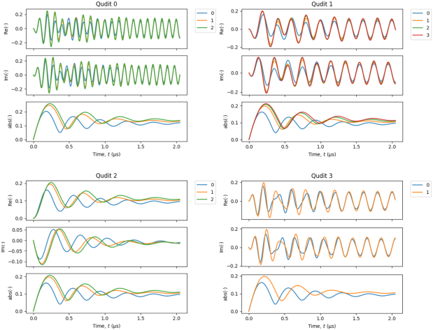
Figure 2: Simulated readout waveforms of 4 qudits. Blue line: state |0>. Orange line: state |1>. Green line: state |2>. Red line: state |3>. -
Measure integration weight
Integration weights of each qudit can be calculated by taking the difference of any 2 reference traces of each qudit, i.e. \(n\) reference traces and \(n(n-1)/2\) integration weights for a qudit with \(n\) states. The reference trace means the readout signal acquired by the Instrument when a qudit prepared in one of the states to be discriminated, for example state |1>, and the rest qudits remain in ground states.
To measure reference traces, all simulated readout pulses will be sent out sequentially defined by the sequence program uploaded using
load_sequencer_program, and recorded by the Scope. The scope is configured usingscopes[n].configure. The SeqC code in the Generator is written such that each state of a qudit is sequentially measured in aforloop, and 4 qudits are therefore measured with 4 subsequentforloops, then the measurement is repeated 2000 times. The Scope records each state with 1 segment and averages it by 2000 times. The data downloaded after the averaging usingscopes[n].readis then reshaped to build qudit reference traces, see Figure 3.In real measurement, only one generator mask (the first argument of
startQA) is needed for one qudit therefore usinggen_mask = (1 << {qudit_idx})in the most innerforloop instead. The setting of integration mask does not matter in this step because the interested signals are the frequency down-converted signal before integration.def simulated_qudit_seqc_program( qudits_num_states, wvfm_idx_mapping, num_repetitions, cycle_time=4e-6, ): seqc_program = textwrap.dedent( f""" const PLAY_ZERO_CYCLES = {cycle_time} * DEVICE_SAMPLE_RATE; info("PLAY_ZERO_CYCLES: %d", PLAY_ZERO_CYCLES); // repeate the measurement repeat({num_repetitions}) {{ """ ) # generate maks to enable the integration of all qudits in the dictionary qa_int_mask = "" for qudit_idx in qudits_num_states.keys(): if qa_int_mask: qa_int_mask += " | " qa_int_mask += f"QA_INT_{qudit_idx}" # generate n (n is the number of qudits) for loops sequentially # in each for loop, specific simulated qudit readout signal is used for each state of a qudit for qudit_idx, num_states in qudits_num_states.items(): first_wave_idx = wvfm_idx_mapping[(qudit_idx, 0)] # index of the first state of the qudit seqc_program += textwrap.indent( textwrap.dedent( f""" // generate and measure refrence traces for qudit {qudit_idx} for(cvar i = 0; i < {num_states}; i++) {{ // mask to enable the playback of the simulated trace // for a specific qudit state cvar gen_mask = (1 << ({first_wave_idx} + i)); // cvar gen_mask = (1 << {qudit_idx}); // for real measurement // wait for the next repetition period playZero(PLAY_ZERO_CYCLES); // play back different waveforms based on the bit mask // and measure the qudit startQA(gen_mask, {qa_int_mask}, true, 0, 0x0); }} """ ), " ", ) seqc_program += textwrap.dedent( """ } // end of repeat({num_repetitions}) """ ) return seqc_program # generate and upload the sequence NUM_REPETITONS = 2000 seqc_program = simulated_qudit_seqc_program( QUDITS_NUM_STATES, WAVEFORM_IDX_MAPPING, num_repetitions=NUM_REPETITONS ) device.qachannels[CHANNEL_INDEX].generator.load_sequencer_program(seqc_program) # configure the scope SCOPE_IDX = 0 # only one scope on the device SCOPE_CHANNEL = 0 # from 0 to 3, 4 in total SCOPE_TRIGGER_CHANNEL = f"chan{CHANNEL_INDEX}seqmon0" # the scope will be triggered by the sequence monitor trigger SCOPE_TRIGGER_DELAY = 200e-9 # start recording 200 ns later after receiving a trigger device.scopes[SCOPE_IDX].configure( input_select={SCOPE_CHANNEL: f"channel{CHANNEL_INDEX}_signal_input"}, num_samples=num_samples, trigger_input=SCOPE_TRIGGER_CHANNEL, num_segments=total_num_states, num_averages=NUM_REPETITONS, trigger_delay=SCOPE_TRIGGER_DELAY, ) # arm the scope device.scopes[SCOPE_CHANNEL].run(single=True) # set the integration delay equals to the scope trigger delay, # so the recorded data can be used for state discrimination directly. device.qachannels[CHANNEL_INDEX].readout.integration.delay(SCOPE_TRIGGER_DELAY) # run the sequencer device.qachannels[CHANNEL_INDEX].generator.enable_sequencer(single=True) # get the scope results and reshape it scope_data, *_ = device.scopes[SCOPE_IDX].read() scope_data_segments = np.reshape( scope_data[SCOPE_CHANNEL], [total_num_states, num_samples] ) # build list of reference traces for each qudit qudits_ref_traces = {} for qudit_idx, num_states in QUDITS_NUM_STATES.items(): ref_traces = [] for state_idx in range(num_states): ref_traces.append( scope_data_segments[WAVEFORM_IDX_MAPPING[(qudit_idx, state_idx)]] ) qudits_ref_traces[qudit_idx] = ref_traces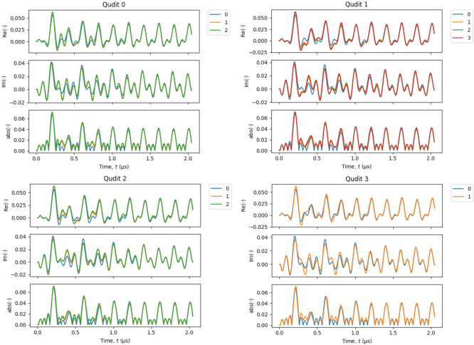
Figure 3: Reference traces of 4 qudits. Blue line: qudit in state |0> and the rest qudits are in state |0>. Orange line: qudit in state |1> and the rest qudits are in state |0>. Green line: qudit in state |2> and the rest qudits are in state |0>. Red line: qudit in state |3> and the rest qudits are state in |0>. All integration weights calculated by the utility function
QuditSettingswith the reference traces are shown in Figure 4.all_qudit_settings = { } for qudit_idx, ref_traces in qudits_ref_traces.items(): all_qudit_settings[qudit_idx] = QuditSettings(ref_traces)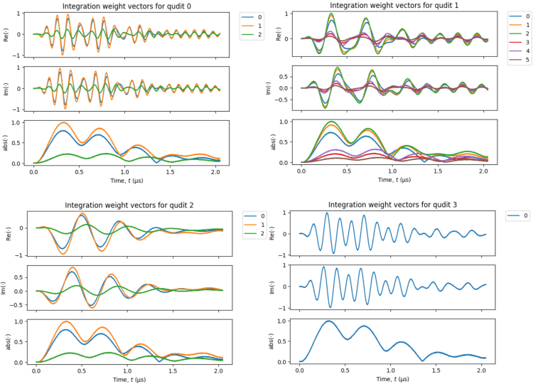
Figure 4: Integration weights of 4 qudits. For a qudit with -
Discriminate qudit state
To discriminate qudit state which is defined by
qudits[n].configure, thresholds and assignment matrix are required. Usingreadout.configure_result_loggerto configure the source of readout result fromresult_of_discrimination.
Thresholds are used to discriminate the results after integration and get 0 or 1, and assignment matrix are used to convert the result after thresholding to the correct digital representation of qudit state are required. These are calculated by the utility functionQuditSettings' too, therefore no additional measurement and manual calculation are needed. [](#shfqa_fig_tutorial_msd_thresholds) shows the histogram of qudits at each state and the thresholds returned from [QuditSettings`]. The script to measure and plot the histogram can be found on GitHub and Online Documentation.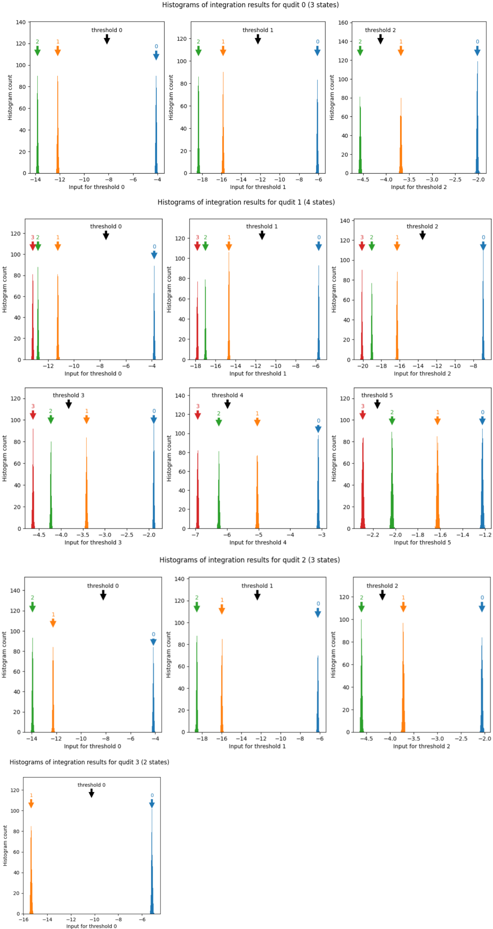
Figure 5: Histogram of qudits at different states and thresholds. Blue: qudit in state |0>. Orange: qudit in state |1>. Green: qudit in state |2>. Red: qudit in state |3>. For qudit with The default state discrimination mode is 2-state discrimination, so the multistate readout mode has to be enabled for this measurement. Before upload new qudit settings, all qudits should be disabled to avoid mixing up of the new and old settings. The readout result source has to be [`result_of_discrimination'] to get digital results representing qudit states. To show how measurement result looks like after state discrimination, the same sequence program used for integration weight measurement, and the simulated qudit readout waveforms are reused. The Instrument sequentially sends out simulated readout signal according to each state of all qudits, and integrates the down-converted signal with \(n-1\) weights and gets \(n(n-1)/2\) integrated results, where \(n\) is the number of qudit states. In the sequence, 4 integrator masks are used for all qudits for simplicity, and only first \(n-1\) integrators are used directly for integration. The \(n(n-1)/2\) results are from the direct integration with \(n-1\) integrators and \((n-1)(n-2)/2\) differences of the integration results. They are discriminated by \(n(n-1)/2\) thresholds, and then converted by the assignment matrix to 2-bit data representing the qudit state. The measurement is repeated 2000 times and the first 24 results of all qudits are shown in Figure 6.
Based on the measured results downloaded using
get_qudits_resultsand expected readout states, the fidelity matrix can be calculated. All calculation and plotting functions are detailed on the Online Documentation page and the GitHub page.# enable the multistate discrimination device.qachannels[CHANNEL_INDEX].readout.multistate.enable(1) # disable all qudits before configure them device.qachannels[CHANNEL_INDEX].readout.multistate.qudits["*"].enable(0) # configure the new qudit settings on the device for qudit_idx, qudit_settings in all_qudit_settings.items(): device.qachannels[CHANNEL_INDEX].readout.multistate.qudits[qudit_idx].configure( qudit_settings ) result_length = NUM_REPETITONS * total_num_states # configure the result logger device.qachannels[CHANNEL_INDEX].readout.configure_result_logger( result_length=result_length, result_source="result_of_discrimination" ) # arm the result logger device.qachannels[CHANNEL_INDEX].readout.run() # run the sequencer device.qachannels[CHANNEL_INDEX].generator.enable_sequencer(single=True) # download the results qudits_results = device.qachannels[ CHANNEL_INDEX ].readout.multistate.get_qudits_results()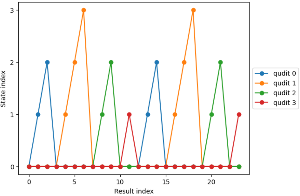
Figure 6: Multistate discrimination of qudits. Only 24 out of 2000 data are shown in the plot. In real measurement, multistate discrimination of multiple qudits can be done in parallel by running a new SeqC program shown below before the above script. In the sequence, output readout waveform is generated by adding up 4 readout waveforms according to 4 qudits, and 12 integrators according to 12 states in total are used. The result after discrimination can be sent to a control instrument for feedback experiment via DIO or via ZSync through a PQSC, e.g. active reset.
seqc_program = textwrap.dedent(
    """
    const PLAY_ZERO_CYCLES = 4e-6 * 2e9;
    // repeate the measurement
    repeat(2000) {
        // wait for the next repetition period
        playZero(PLAY_ZERO_CYCLES);

        // play back readout waveform of 4 qudits
        // and measure the qudits
        startQA(QA_GEN_0 | QA_GEN_1 | QA_GEN_2 | QA_GEN_3, QA_INT_ALL, true,  0, 0x0);
    }
    """
)