Readout Pulse Generator Tab
The Readout Pulse Generator tab is the main control panel for readout measurement sequences. It is available on all SHFQA+ Instruments.
Features Overview
- 1 Sequencer for each Readout Channel
- 8 or 16 readout waveform memory slots, 4 kSa for each memory slot
- 8 or 16 integration weights memory slots, 4 kSa for each memory slot
- Sequence branching
- Access to multiple internal triggers
- Interface to DIO and ZSync for synchronization and feedback
- High-level programming language
- Display waveforms in waveform memory and integration weight units
Description
| Control/Tool | Option/Range | Description |
|---|---|---|
| Generator | Generate readout measurement sequences. |
The Sequencer Editor can be considered the central control unit of
the SHFQA+ as it has access to the playback of the Waveform Memories to
generate Readout Pulses, the start of the Integration of the Readout
Signals from the experiment and the communication with additional
devices through the DIO or ZSync. The programming language SeqC is
based on C and specified in detail in SeqC
language.
In contrast to other AWG Sequencers, e.g. from the HDAWG, it does not
provide writing access to the Waveform Memories and hence does not come
with predefined waveforms. The stricter separation between Sequencer and
Waveform Memory allows implementation of more advanced and
application-specific features, e.g. Time-Staggered Readout, while still
providing real-time sequencing.
The Sequencer features a compiler which translates the high-level sequence program (SeqC) into machine instructions to be stored in the Instrument sequencer memory. The sequence program is written using high-level control structures and syntax that are inspired by human language, whereas machine instructions reflect exactly what happens on the hardware level. Writing the sequence program using SeqC represents a more natural and efficient way of working in comparison to writing lists of machine instructions, which is the traditional way of programming AWGs. Concretely, the improvements rely on features such as:
- Waveform playback and sequencing in a single script
- Easily readable syntax and naming for run-time variables and constants
- Definition of user functions and procedures for advanced structuring
- Syntax validation
By design, there is no one-to-one link between the list of statements in the high-level language and the list of instructions executed by the Sequencer. In order to understand the execution timing, it’s helpful to consider the internal architecture of the Readout Pulse Generator, consisting of the Sequencer itself, and the Waveform Memory including a Waveform Player.
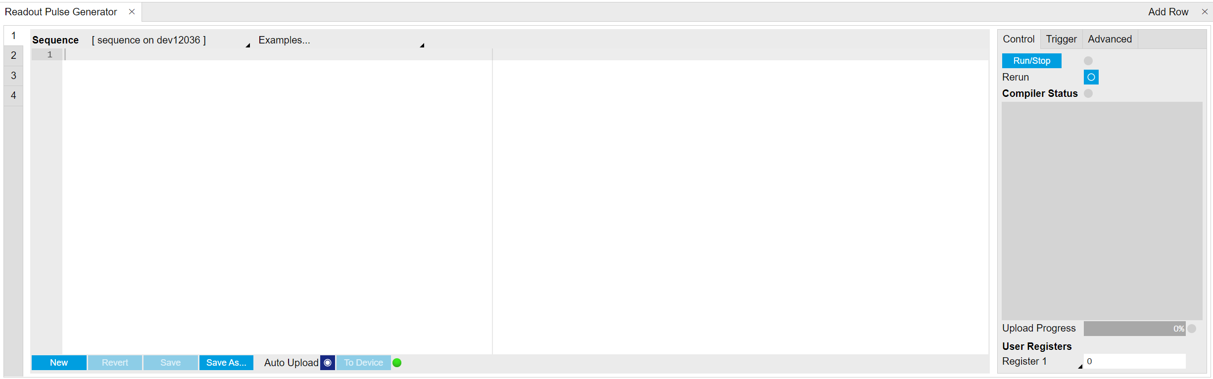
On the Control sub-tab the user configures signal parameters and controls the execution of the sequencer. The sequencer can be started by clicking on Run/Stop. When enabling the Rerun button, the Sequencer will be restarted automatically when its program completes. The Compiler Status shows whether compilation is successful, or generated warnings or errors.
On the Trigger sub-tab users can configure the trigger inputs of the sequencer and control the Hardware Trigger Engine functionality of the Instrument. The sequencer can be triggered by Digital trigger source including DIO trigger or ZSync trigger. Only Digital trigger and DIO trigger are configured in this sub-tab. ZSync trigger is configured in Device Tab. There are 2 digital triggers that can be configured for each sequencer. The options of Digital trigger source include,
- the physical trigger input A and B of all channels,
- the sequencer trigger defined in all sequencers, such as through the command setTrigger,
- the readout done of all channels,
- the software trigger.
The sequencer can also be triggered by DIO trigger input with chosen Valid bit and Polarity (see DIO Tab)
The Advanced sub-tab displays the compiled list of sequencer instructions and the current state of the sequencer on the Instrument. This can help an advanced user in debugging a sequence program and understanding its execution.
Sequencer Operation
Every pulse sequence requires defining a SeqC program. For an example of
how to define and upload a sequence, see the Pulse Spectroscopy
Tutorial. The status of the upload can be monitored via
the Ready
node. Once it
returns true, the compilation is successful and the program is
transferred to the device. If the compilation fails, the Status
node
will display debug messages.
After successful uploading of a sequence to the Instrument, the
Sequencer can be started using the Enable
node.
If the Sequencer should wait for a Trigger Input Signal, it can either directly wait for a ZSync Trigger, or access the Auxiliary Triggers.
With the SHFQA+ utility functions, the above-mentioned steps can be realized by a single function. A set of Python API examples can be found in GitHub
All nodes for the Sequencer can be accessed through the node trees,
/dev..../qachannels/n/generator/...
and
/dev..../qachannels/n/generator/sequencer/....
SeqC
The syntax of the LabOne AWG Sequencer programming language is based on C, but with a few simplifications. Each statement is concluded with a semicolon, several statements can be grouped with curly brackets, and comment lines are identified with a double slash.
The following example shows some of the fundamental functionalities:
repeated playback, triggering, and single/dual-channel waveform playback
and readout. See Tutorials for a step-by-step
introduction with more examples. The command waitZSyncTrigger is used
to wait a trigger from PQSC Programmable Quantum System
Controller via
ZSync. Alternatively, an external digital trigger from the front panel
or an internal trigger can also be used to start the sequence by the
command waitDigTrigger. The first playZero sets the delay
between the trigger and the first readout pulse, and the second
playZero sets the delay between the first and the second readout
pulse. The command startQA sends out internal triggers to play
readout pulses saved in the waveform memory, to start integrations with
waveforms saved in the integration weight units, and to send a Sequencer
monitor trigger which can be used to trigger the Scope. The third
playZero ensures that the previous commands playZero are
finished.
// repeat sequence 100 times
repeat (100) {
    // wait for a trigger over ZSync. Assume the trigger period is longer than the cycle time
    waitZSyncTrigger();

    // alternatively wait for a trigger from digital trigger 1
    // waitDigTrigger(1);

    // wait for 4096 Samples between the trigger and the first readout pulse
    // Note: this playZero command does not yet block the sequencer
    playZero(4096);

    // define how many samples to wait between the two upcoming startQA commands
    // Note: this command blocks the sequencer until the previous playZero command is finished
    playZero(4096);

    // play the pulse stored in Waveform Memory slot 0 and read out using Integration Weight 0
    startQA(QA_GEN_0, QA_INT_0, true,  0x0, 0x0);

    // minimal duration playZero command to wait until the previous playZero command is finished
    playZero(32);

    // play the pulse stored in Waveform Memory slot 0, 1 and 2, and read out using all Integration Weights
    startQA(QA_GEN_0|QA_GEN_1|QA_GEN_2, QA_INT_ALL, true,  0x0, 0x0);
}
Keywords and Comments
The following table lists the keywords used in the LabOne AWG Sequencer language.
| Keyword | Description |
|---|---|
const |
Constant declaration |
var |
Integer variable declaration |
cvar |
Compile-time variable declaration |
string |
Constant string declaration |
true |
Boolean true constant |
false |
Boolean false constant |
for |
For-loop declaration |
while |
While-loop declaration |
repeat |
Repeat-loop declaration |
if |
If-statement |
else |
Else-part of an if-statement |
switch |
Switch-statement |
case |
Case-statement within a switch |
default |
Default-statement within a switch |
return |
Return from function or procedure, optionally with a return value |
The following code example shows how to use comments.
const a = 10; // This is a line comment. Everything between the double
              // slash and the end of the line will be ignored.

/* This is a block comment. Everything between the start-of-block-comment and end-of-block-comment markers is ignored.

For example, the following statement will be ignored by the compiler.

const b = 100;
*/
Constants and Variables
Constants may be used to make the program more readable. They may be
of integer or floating-point type. It must be possible for the compiler
to compute the value of a constant at compile time, i.e., on the host
computer. Constants are declared using the const keyword.
Compile-time variables may be used in computations and loop
iterations during compile time, e.g. to create large numbers of
waveforms in a loop. They may be of integer or floating-point type. They
are used in a similar way as constants, except that they can change
their value during compile time operations. Compile-time variables are
declared using the cvar keyword.
Variables may be used for making simple computations during run
time, i.e., on the Instrument. The Sequencer supports integer variables,
addition, and subtraction. Not supported are floating-point variables,
multiplication, and division. Typical uses of variables are to step
waiting times, to output DIO values, or to tag digital measurement data
with a numerical identifier. Variables are declared using the var
keyword.
The following code example shows how to use variables.
var b = 100; // Create and initialize a variable

// Repeat the following block of statements 100 times
repeat (100) {
    b = b + 1; // Increment b
    wait(b);   // Wait 'b' cycles
}
The following table shows the predefined constants. These constants are intended to be used as arguments in certain run-time evaluated functions that encode device parameters with integer numbers.
Constants whose value is marked as "opaque" are meant to always be used instead of their numerical value.
| Name | Value | Description |
|---|---|---|
| M_E | 2.71828182845904523536028747135266250 | e |
| M_LOG2E | 1.44269504088896340735992468100189214 | log2(e) |
| M_LOG10E | 0.434294481903251827651128918916605082 | log10(e) |
| M_LN2 | 0.693147180559945309417232121458176568 | loge(2) |
| M_LN10 | 2.30258509299404568401799145468436421 | loge(10) |
| M_PI | 3.14159265358979323846264338327950288 | pi |
| M_PI_2 | 1.57079632679489661923132169163975144 | pi/2 |
| M_PI_4 | 0.785398163397448309615660845819875721 | pi/4 |
| M_1_PI | 0.318309886183790671537767526745028724 | 1/pi |
| M_2_PI | 0.636619772367581343075535053490057448 | 2/pi |
| M_2_SQRTPI | 1.12837916709551257389615890312154517 | 2/sqrt(pi) |
| M_SQRT2 | 1.41421356237309504880168872420969808 | sqrt(2) |
| M_SQRT1_2 | 0.707106781186547524400844362104849039 | 1/sqrt(2) |
Numbers can be expressed using either of the following formatting.
const a = 10;           // Integer notation
const b = -10;          // Negative number
const h = 0xdeadbeef;   // Hexadecimal integer
const bin = 0b10101;    // Binary integer
const f = 0.1e-3;       // Floating point number.
const not_float = 10e3; // Not a floating point number
Booleans are specified with the keywords true and false.
Furthermore, all numbers that evaluate to a nonzero value are considered
true. All numbers that evaluate to zero are considered false.
Strings are delimited using "" and are interpreted as constants.
Strings may be concatenated using the + operator.
string AWG_PATH = "awgs/0/";
string AWG_GAIN_PATH = AWG_PATH + "gains/0";
Waveform Playback and Predefined Functions
The following table contains the definition of functions for waveform playback and other purposes.
void setDIO(var value) 
Writes the value as a 32-bit value to the DIO bus.
The value can be either a const or a var value. Configure the Mode setting in the DIO tab when using this command. The DIO interface speed of 50 MHz limits the rate at which the DIO output value is updated.
Args:
value:The value to write to the DIO (const or var)
var getDIOTriggered() 
Reads a 32-bit value from the DIO bus as recorded at the last DIO trigger position.
Returns:
var containing the read value
void setTrigger(var value) 
Sets the Sequencer Trigger output signals.
The state of the two Sequencer Trigger output signals is defined by the bits in the binary representation of the integer value. Allowed parameter values are 0 to 3. For higher integer values, only the two least-significant bits will have an effect.Binary notation of the form 0b00 is recommended for readability.
Args:
value:to be written to the trigger distribution unit
void wait(var cycles) 
Waits for the given number of Sequencer clock cycles (4 ns per cycle). The execution of the instruction adds an offset of 2 clock cycles, i.e., the statement wait(3) leads to a waiting time of 5 * 4 ns = 20 ns.
Note: the minimum waiting time amounts to 3 cycles, which means that wait(0) and wait(1) will both result in a waiting time of 3 * 4 ns = 12 ns.
Args:
cycles:number of cycles to wait
void waitDIOTrigger() 
Waits until the DIO interface trigger is active. The trigger is specified by the Strobe Index and Strobe Slope settings in the AWG Sequencer tab.
var getDigTrigger(const index) 
Gets the state of the indexed Digital Trigger input (1 or 2).
The physical signal connected to the Digital Trigger input is to be configured in the Readout section of the Quantum Analyzer Setup tab.
Args:
index:index of the Digital Trigger input to be read; can be either 1 or 2
Returns:
trigger state, either 0 or 1
void error(string msg,...) 
Throws the given error message when reached.
Args:
msg:Message to be displayed
void info(string msg,...) 
Returns the specified message when reached.
Args:
msg:Message to be displayed
void setUserReg(const register, var value) 
Writes a value to one of the User Registers (indexed 0 to 15).
The User Registers may be used for communicating information to the LabOne User Interface or a running API program.
Args:
-
register:The register index (0 to 15) to be written to -
value:The integer value to be written
var getUserReg(const register) 
Reads the value from one of the User Registers (indexed 0 to 15). The User Registers may be used for communicating information to the LabOne User Interface or a running API program.
Args:
register:The register to be read (0 to 15)
Returns:
current register value
void playZero(var samples) 
Zero Playback, which can be used to specify spacings in number of samples at the sample rate of 2 GSa/s between the execution times of commands, such as startQA. Each playZero command blocks the execution of subsequent commands when a previous Zero Playback is already running. Note: the playback of actual waveforms with the startQA command happens in parallel to the Zero Playback, in contrast to the HDAWG and SHFSG!
Args:
samples:Number of samples for the spacing. The minimal spacing is 32 samples and the granularity is 16 samples.
void playZero(var samples, const rate) 
Zero Playback, which can be used to specify spacings in number of samples between the execution times of commands, such as startQA. Each playZero command blocks the execution of subsequent commands when a previous Zero Playback is already running. Note: the playback of actual waveforms with the startQA command happens in parallel to the Zero Playback, in contrast to the HDAWG and SHFSG!
Args:
-
rate:Sample rate with which the spacing is specified. Divides the device sample rate by 2^rate. Note: this rate does not affect the sample rate of the QA waveform generator (startQA command). -
samples:Number of samples for the spacing. The minimal spacing is 32 samples and the granularity is 16 samples.
void waitDigTrigger(const index) 
Waits for the reception of a trigger signal on the indexed Digital Trigger (index 1 or 2). The physical signals connected to the two AWG Digital Triggers are to be configured in the Trigger sub-tab of the AWG Sequencer tab. The Digital Triggers are configured separately for each AWG Core.
Args:
index:Index of the digital trigger input; can be either 1 or 2.
void configFreqSweep(const oscillator_index, const freq_start, const freq_increment) 
Configures a frequency sweep.
Args:
-
freq_increment:Specify how much to increment the frequency for each step of the sweep [Hz] -
freq_start:Specify the start frequency value for the sweep [Hz] -
oscillator_index:Index of the oscillator that will be used for the sweep
void resetOscPhase(const mask) 
Reset the phase of the oscillators specified by the binary mask argument. Each AWG core can access the oscillators of its QA/SGCHANNEL.
Args:
mask:one-hot encoding to reset phase of individual oscillators
void resetOscPhase() 
Reset the phase of all oscillators controllable by the AWG core.
Reset the phase of the oscillator controllable by the sequencer. Each sequencer can control the oscillator of its QACHANNEL.
void setSweepStep(const oscillator_index, var sweep_index) 
Executes a step within a frequency sweep.
Args:
-
oscillator_index:Index of the oscillator that will be used for the sweep -
sweep_index:Sets the step index, from which the frequency is set
void setOscFreq(const oscillator_index, const freq) 
Configures the frequency of an oscillator.
Args:
-
freq:Frequency to be set [Hz] -
oscillator_index:Index of oscillator
var getFeedback(const data_type) 
Read the last received feedback message. The argument specify which data the function should return.
Args:
data_type:Specifies which data the function should return: ZSYNC_DATA_RAW: Returns the last ZSync message received.
Returns:
var containing the read value
var getFeedback(const data_type, var wait_cycles) 
Read the last received feedback message. The argument specify which data the function should return.
Args:
-
data_type:Specifies which data the function should return: ZSYNC_DATA_RAW: Returns the last ZSync message received. -
wait_cycles:Wait for the specified number of cycles after the most recent waitZSyncTrigger() instruction.
Returns:
var containing the read value
void waitZSyncTrigger() 
Waits for a trigger over ZSync.
void startQA(const waveform_generator_mask, const weighted_integrator_mask, const monitor, const result_address, const trigger) 
Starts the Quantum Analysis (QA) Readout Waveform Generation, Integration, and Result units.
Args:
-
monitor:Enable the Sequencer Monitor Trigger, which is issued simultaneously with the start of the weighted integration units. In addition to setting this argument to true, the Sequencer Monitor Trigger must be selected as trigger source for the SHFQA Scope in order to align the start of the time trace to the start of the weighted integration. Default: false. -
result_address:Specify the address of the PQSC readout register in which to store the readout result from this SHFQA. Please refer to the PQSC user manual for more details. Default: 0x0 -
trigger:Sets the sequencer trigger output in the same manner as the setTrigger() command. Default: 0b00 -
waveform_generator_mask:Readout Waveform Generator unit enable mask. Providing a value for this argument is mandatory. The mask can be specified using the predefined constants QA_GEN_n, where n is an index ranging from 0 to 15, except for the 2-channel SHFQA without 16W option, where the range only spans from 0 to 7. To construct more elaborate masks that enable multiple units, combine these predefined constants using the operator | (bit-wise OR). The constant QA_GEN_ALL can be used to enable all units simultaneously. NOTE: the signals from simultaneously enabled Waveform Generation units are combined by a digital adder. -
weighted_integrator_mask:Integration unit enable mask, default: QA_INT_ALL The mask can be specified using the predefined constants QA_INT_n, where n is an index ranging from 0 to 15, except for the 2-channel SHFQA without 16W option, where the range only spans from 0 to 7. To construct more elaborate masks that enable multiple units, combine these predefined constants using the operator | (bit-wise OR). The constant QA_INT_ALL can be used to enable all units simultaneously.
Expressions
Expressions may be used for making computations based on mathematical functions and operators. There are two kinds of expressions: those evaluated at compile time (when the sequencer program is compiled on the computer), and those evaluated at run time.
Compile-time evaluated expressions only involve constants (const)
or compile-time variables (cvar) and can be computed at compile time
by the host computer. Such expressions can make use of standard
mathematical functions and floating point arithmetic.
Run-time evaluated expressions involve variables (var) and are
evaluated by the Sequencer on the Instrument. Due to the limited
computational capabilities of the Sequencer, these expressions may only
operate on integer numbers and there are less operators available than
at compile time.
The following table contains the list of mathematical functions supported at compile time.
| Function | Description |
|---|---|
| const abs(const c) | absolute value |
| const acos(const c) | inverse cosine |
| const acosh(const c) | hyperbolic inverse cosine |
| const asin(const c) | inverse sine |
| const asinh(const c) | hyperbolic inverse sine |
| const atan(const c) | inverse tangent |
| const atanh(const c) | hyperbolic inverse tangent |
| const cos(const c) | cosine |
| const cosh(const c) | hyperbolic cosine |
| const exp(const c) | exponential function |
| const ln(const c) | logarithm to base e (2.71828...) |
| const log(const c) | logarithm to the base 10 |
| const log2(const c) | logarithm to the base 2 |
| const log10(const c) | logarithm to the base 10 |
| const sign(const c) | sign function -1 if x<0; 1 if x>0 |
| const sin(const c) | sine |
| const sinh(const c) | hyperbolic sine |
| const sqrt(const c) | square root |
| const tan(const c) | tangent |
| const tanh(const c) | hyperbolic tangent |
| const ceil(const c) | smallest integer value not less than the argument |
| const round(const c) | round to nearest integer |
| const floor(const c) | largest integer value not greater than the argument |
| const avg(const c1, const c2,...) | mean value of all arguments |
| const max(const c1, const c2,...) | maximum of all arguments |
| const min(const c1, const c2,...) | minimum of all arguments |
| const pow(const base, const exp) | first argument raised to the power of second argument |
| const sum(const c1, const c2,...) | sum of all arguments |
The following table contains the list of predefined mathematical constants. These can be used for convenience in compile-time evaluated expressions.
| Name | Value | Description |
|---|---|---|
| AWG_RATE_2000MHZ | 0 | Constant to set Sampling Rate to 2.0 GHz. |
| AWG_RATE_1000MHZ | 1 | Constant to set Sampling Rate to 1.0 GHz. |
| AWG_RATE_500MHZ | 2 | Constant to set Sampling Rate to 500 MHz. |
| AWG_RATE_250MHZ | 3 | Constant to set Sampling Rate to 250 MHz. |
| AWG_RATE_125MHZ | 4 | Constant to set Sampling Rate to 125 MHz. |
| AWG_RATE_62P5MHZ | 5 | Constant to set Sampling Rate to 62.5 MHz. |
| AWG_RATE_31P25MHZ | 6 | Constant to set Sampling Rate to 31.25 MHz. |
| AWG_RATE_15P63MHZ | 7 | Constant to set Sampling Rate to 15.63 MHz. |
| AWG_RATE_7P81MHZ | 8 | Constant to set Sampling Rate to 7.81 MHz. |
| AWG_RATE_3P9MHZ | 9 | Constant to set Sampling Rate to 3.9 MHz. |
| AWG_RATE_1P95MHZ | 10 | Constant to set Sampling Rate to 1.95 MHz. |
| AWG_RATE_976KHZ | 11 | Constant to set Sampling Rate to 976 kHz. |
| AWG_RATE_488KHZ | 12 | Constant to set Sampling Rate to 488 kHz. |
| AWG_RATE_244KHZ | 13 | Constant to set Sampling Rate to 244 kHz. |
| DEVICE_SAMPLE_RATE | <actual device sample rate> | |
| ZSYNC_DATA_RAW | opaque | Constant to use as argument to getFeedback. Returns the last ZSync message received. |
| QA_INT_0 | (1 << 0) | Constant to enable Integration unit 0 in the Integration unit enable mask of the function startQA(). To construct more elaborate masks that enable multiple units, combine these predefined constants using the operator |
| QA_INT_1 | (1 << 1) | Constant to enable Integration unit 1 in the Integration unit enable mask of the function startQA(). To construct more elaborate masks that enable multiple units, combine these predefined constants using the operator |
| QA_INT_2 | (1 << 2) | Constant to enable Integration unit 2 in the Integration unit enable mask of the function startQA(). To construct more elaborate masks that enable multiple units, combine these predefined constants using the operator |
| QA_INT_3 | (1 << 3) | Constant to enable Integration unit 3 in the Integration unit enable mask of the function startQA(). To construct more elaborate masks that enable multiple units, combine these predefined constants using the operator |
| QA_INT_4 | (1 << 4) | Constant to enable Integration unit 4 in the Integration unit enable mask of the function startQA(). To construct more elaborate masks that enable multiple units, combine these predefined constants using the operator |
| QA_INT_5 | (1 << 5) | Constant to enable Integration unit 5 in the Integration unit enable mask of the function startQA(). To construct more elaborate masks that enable multiple units, combine these predefined constants using the operator |
| QA_INT_6 | (1 << 6) | Constant to enable Integration unit 6 in the Integration unit enable mask of the function startQA(). To construct more elaborate masks that enable multiple units, combine these predefined constants using the operator |
| QA_INT_7 | (1 << 7) | Constant to enable Integration unit 7 in the Integration unit enable mask of the function startQA(). To construct more elaborate masks that enable multiple units, combine these predefined constants using the operator |
| QA_INT_8 | (1 << 8) | Constant to enable Integration unit 8 in the Integration unit enable mask of the function startQA(). To construct more elaborate masks that enable multiple units, combine these predefined constants using the operator |
| QA_INT_9 | (1 << 9) | Constant to enable Integration unit 9 in the Integration unit enable mask of the function startQA(). To construct more elaborate masks that enable multiple units, combine these predefined constants using the operator |
| QA_INT_10 | (1 << 10) | Constant to enable Integration unit 10 in the Integration unit enable mask of the function startQA(). To construct more elaborate masks that enable multiple units, combine these predefined constants using the operator |
| QA_INT_11 | (1 << 11) | Constant to enable Integration unit 11 in the Integration unit enable mask of the function startQA(). To construct more elaborate masks that enable multiple units, combine these predefined constants using the operator |
| QA_INT_12 | (1 << 12) | Constant to enable Integration unit 12 in the Integration unit enable mask of the function startQA(). To construct more elaborate masks that enable multiple units, combine these predefined constants using the operator |
| QA_INT_13 | (1 << 13) | Constant to enable Integration unit 13 in the Integration unit enable mask of the function startQA(). To construct more elaborate masks that enable multiple units, combine these predefined constants using the operator |
| QA_INT_14 | (1 << 14) | Constant to enable Integration unit 14 in the Integration unit enable mask of the function startQA(). To construct more elaborate masks that enable multiple units, combine these predefined constants using the operator |
| QA_INT_15 | (1 << 15) | Constant to enable Integration unit 15 in the Integration unit enable mask of the function startQA(). To construct more elaborate masks that enable multiple units, combine these predefined constants using the operator |
| QA_INT_ALL | (1 << 16) - 1 | Constant to enable all Integration units in the Integration unit enable mask of the function startQA(). |
| QA_INT_NONE | 0 | Constant to be used in the Integration unit enable mask of the function startQA() to represent the scenario when no integrator is enabled. |
| QA_GEN_0 | (1 << 0) | Constant to enable Readout Waveform Generator unit 0 in the Readout Waveform Generator unit enable mask of the function startQA(). To construct more elaborate masks that enable multiple units, combine these predefined constants using the operator |
| QA_GEN_1 | (1 << 1) | Constant to enable Readout Waveform Generator unit 1 in the Readout Waveform Generator unit enable mask of the function startQA(). To construct more elaborate masks that enable multiple units, combine these predefined constants using the operator |
| QA_GEN_2 | (1 << 2) | Constant to enable Readout Waveform Generator unit 2 in the Readout Waveform Generator unit enable mask of the function startQA(). To construct more elaborate masks that enable multiple units, combine these predefined constants using the operator |
| QA_GEN_3 | (1 << 3) | Constant to enable Readout Waveform Generator unit 3 in the Readout Waveform Generator unit enable mask of the function startQA(). To construct more elaborate masks that enable multiple units, combine these predefined constants using the operator |
| QA_GEN_4 | (1 << 4) | Constant to enable Readout Waveform Generator unit 4 in the Readout Waveform Generator unit enable mask of the function startQA(). To construct more elaborate masks that enable multiple units, combine these predefined constants using the operator |
| QA_GEN_5 | (1 << 5) | Constant to enable Readout Waveform Generator unit 5 in the Readout Waveform Generator unit enable mask of the function startQA(). To construct more elaborate masks that enable multiple units, combine these predefined constants using the operator |
| QA_GEN_6 | (1 << 6) | Constant to enable Readout Waveform Generator unit 6 in the Readout Waveform Generator unit enable mask of the function startQA(). To construct more elaborate masks that enable multiple units, combine these predefined constants using the operator |
| QA_GEN_7 | (1 << 7) | Constant to enable Readout Waveform Generator unit 7 in the Readout Waveform Generator unit enable mask of the function startQA(). To construct more elaborate masks that enable multiple units, combine these predefined constants using the operator |
| QA_GEN_8 | (1 << 8) | Constant to enable Readout Waveform Generator unit 8 in the Readout Waveform Generator unit enable mask of the function startQA(). To construct more elaborate masks that enable multiple units, combine these predefined constants using the operator |
| QA_GEN_9 | (1 << 9) | Constant to enable Readout Waveform Generator unit 9 in the Readout Waveform Generator unit enable mask of the function startQA(). To construct more elaborate masks that enable multiple units, combine these predefined constants using the operator |
| QA_GEN_10 | (1 << 10) | Constant to enable Readout Waveform Generator unit 10 in the Readout Waveform Generator unit enable mask of the function startQA(). To construct more elaborate masks that enable multiple units, combine these predefined constants using the operator |
| QA_GEN_11 | (1 << 11) | Constant to enable Readout Waveform Generator unit 11 in the Readout Waveform Generator unit enable mask of the function startQA(). To construct more elaborate masks that enable multiple units, combine these predefined constants using the operator |
| QA_GEN_12 | (1 << 12) | Constant to enable Readout Waveform Generator unit 12 in the Readout Waveform Generator unit enable mask of the function startQA(). To construct more elaborate masks that enable multiple units, combine these predefined constants using the operator |
| QA_GEN_13 | (1 << 13) | Constant to enable Readout Waveform Generator unit 13 in the Readout Waveform Generator unit enable mask of the function startQA(). To construct more elaborate masks that enable multiple units, combine these predefined constants using the operator |
| QA_GEN_14 | (1 << 14) | Constant to enable Readout Waveform Generator unit 14 in the Readout Waveform Generator unit enable mask of the function startQA(). To construct more elaborate masks that enable multiple units, combine these predefined constants using the operator |
| QA_GEN_15 | (1 << 15) | Constant to enable Readout Waveform Generator unit 15 in the Readout Waveform Generator unit enable mask of the function startQA(). To construct more elaborate masks that enable multiple units, combine these predefined constants using the operator |
| QA_GEN_ALL | (1 << 16) - 1 | Constant to enable all Waveform Generator units in the waveform generator unit enable mask of the function startQA(). |
| QA_GEN_NONE | 0 | Constant to be used in the Waveform Generator unit enable mask of the function startQA() to represent the scenario when no Waveform Generator is enabled. |
Control Structures
Functions may be declared using the var keyword. Procedures
may be declared using the void keyword. Functions must return a value,
which should be specified using the return keyword. Procedures can not
return values. Functions and procedures may be declared with an
arbitrary number of arguments. The return keyword may also be used
without arguments to return from an arbitrary point within the function
or procedure. Functions and procedures may contain variable and constant
declarations. These declarations are local to the scope of the function
or procedure.
var function_name(argument1, argument2, ...) {
    // Statements to be executed as part of the function.
    return constant-or-variable;
}
void procedure_name(argument1, argument2, ...) {
    // Statements to be executed as part of the procedure.

    // Optional return statement
    return;
}
An if-then-else structure is used to create a conditional branching point in a sequencer program.
// If-then-else statement syntax
if (expression) {
    // Statements to execute if 'expression' evaluates to 'true'.
} else {
    // Statements to execute if 'expression' evaluates to 'false'.
}

// If-then-else statement short syntax
(expression)?(statement if true):(statement if false)

// If-then-else statement example
const REQUEST_BIT = 0x0001;
const ACKNOWLEDGE_BIT = 0x0002;
const IDLE_BIT = 0x8000;
var dio = getDIO();

if (dio & REQUEST_BIT) {
    dio = dio | ACKNOWLEDGE_BIT;
    setDIO(dio);
} else {
    dio = dio | IDLE_BIT;
    setDIO(dio);
}
A switch-case structure serves to define a conditional branching
point similarly to the if-then-else statement, but is used to split
the sequencer thread into more than two branches. Unlike the
if-then-else structure, the switch statement is synchronous, which
means that the execution time is the same for all branches and
determined by the execution time of the longest branch. If no default
case is provided and no case matches the condition, all cases will be
skipped. The case arguments need to be of type const.
// Switch-case statement syntax
switch (expression) {
    case const-expression:
        expression;
    ...
default:
    expression;
}
// Switch-case statement example
switch (getDIO()) {
    case 0:
        startQA(QA_GEN_0, QA_INT_0, true,  0x0, 0x0);
    case 1:
        startQA(QA_GEN_1, QA_INT_1, true,  0x0, 0x0);
    case 2:
        startQA(QA_GEN_2, QA_INT_2, true,  0x0, 0x0);
    default:
        startQA(QA_GEN_3, QA_INT_3, true,  0x0, 0x0);
}
The for loop is used to iterate through a code block several times.
The initialization statement is executed before the loop starts. The
end-expression is evaluated at the start of each iteration and
determines when the loop should stop. The loop is executed as long as
this expression is true. The iteration-expression is executed at the
end of each loop iteration. Depending on how the for loop is set up,
it can be either evaluated at compile time or at run time. For a
run-time evaluated for loop, use the var data type as a loop index.
To ensure that a loop is evaluated at compile time, use the cvar data
type as a loop index. Furthermore, the compile-time for loop should
only contain waveform generation/editing operations and it can’t contain
any variables of type var.
The following code example shows both versions of the loop.
// For loop syntax
for (initialization; end-expression; iteration-expression) {
    // Statements to execute while end-expression evaluates to true
}

// For loop example (compile-time execution)
cvar i;
wave w_pulses;
for (i = 0; i < 10; i = i + 1) {
    startQA(QA_GEN_0<<1, QA_INT_0, true,  0x0, 0x0);
}

// For loop example (run-time execution)
var k;
var j;
for (j = 9; j >= 0; j = j - 1) {
    startQA(QA_GEN_0, QA_INT_0, true,  0x0, 0x0);
    k += j;
}
The while loop is a simplified version of the for loop. The
end-expression is evaluated at the start of each loop iteration. The
contents of the loop are executed as long as this expression is true.
Like the for loop, this loop comes in a compile-time version (if the
end-expression involves only cvar and const) and in a run-time
version (if the end-expression involves also var data types).
// While loop syntax
while (end-expression) {
    // Statements to execute while end-expression evaluates to true
}

// While loop example
const STOP_BIT = 0x8000;
var run = 1;
var i = 0;
var dio = 0;
while (run) {
    dio = getDIO();
    run = dio & STOP_BIT;
    dio = dio | (i & 0xff);
    setDIO(dio);
    i = i + 1;
}
The repeat loop is a simplified version of the for loop. It repeats
the contents of the loop a fixed number of times. In contrast to the
for loop, the repetition number of the repeat loop must be known at
compile time, i.e., const-expression can only depend on constants and
not on variables. Unlike the for and the while loop, this loop comes
only in a run-time version. Thus, no cvar data types may be modified
in the loop body.
// Repeat loop syntax
repeat (constant-expression) {
    // Statements to execute
}

// Repeat loop example
repeat (100) {
    setDIO(0x1);
    wait(10);
    setDIO(0x0);
    wait(10);
}
Waveform Memory
The Waveform Memory stores the different complex-valued arbitrary
waveforms that are used to readout the qubits. They can be accessed
through /dev..../qachannels/n/generator/waveforms/n/wave and
have a maximal length of 4096 samples and a vertical range between -1
and 1 relative to the full scale of the Output Range.
Functional Elements
| Control/Tool | Option/Range | Description |
|---|---|---|
| Start | ON/OFF | Run the Generator Sequencer. |
| Rerun | ON/OFF | Puts the Sequencer into single-shot mode or rerun mode. |
| Status | Display compiler errors and warnings. | |
| Compile Status | grey/green/yellow/red | Sequence program compilation status. Grey: No compilation started yet. Green: Compilation successful. Yellow: Compiler warnings (see status field). Red: Compilation failed (see status field). |
| Upload Progress | 0% to 100% | The percentage of the sequencer program already uploaded to the device. |
| Upload Status | grey/yellow/green | Indicates the upload status of the compiled sequence. Grey: Nothing has been uploaded. Yellow: Upload in progress. Green: Compiled sequence has been uploaded. |
| Register Selector | 1 to 16 | Select the number of the user register value to be edited. |
| Register | 0 to \(2^{32}\) | Integer user register value. The sequencer has reading and writing access to the user register values during run time. |
| Input File | External source code file to be compiled. | |
| Example File | Load pre-installed example sequence program. | |
| New | Create a new sequence program. | |
| Revert | Undo the changes made to the current program and go back to the contents of the original file. | |
| Save (Ctrl+S) | Compile and save the current program displayed in the Sequence Editor. Overwrites the original file. | |
| Save As... (Ctrl+Shift+S) | Compile and save the current program displayed in the Sequence Editor under a new name. | |
| Automatic Upload | ON / OFF | If enabled, the sequence program is automatically uploaded to the device after clicking Save and if the compilation was successful. |
| To Device | Sequence program will be compiled and, if the compilation was successful, uploaded to the device. |
| Control/Tool | Option/Range | Description |
|---|---|---|
| Status | grey/green/yellow/red | Displays the status of the sequence on the Instrument. Off: Ready, not running. Green: Running, not waiting for any trigger event. Yellow: Running, waiting for a trigger event. Red: Not Ready. |
| Digital Trigger | 1 or 2 | Choose Digital Trigger 1 or Digital Trigger 2 |
| Signal | Selects Digital Trigger source signal. Navigate through the tree view that appears and click on the required signal. | |
| Valid Index | Selects the index n of the DIO interface bit (notation DIO[n] in the Specification chapter of the User Manual) to be used as a VALID signal input, i.e. a qualifier indicating that a valid codeword is available on the DIO interface. | |
| Valid Polarity | Polarity of the VALID bit that indicates that a codeword is available on the DIO interface. | |
| Low | VALID bit must be logical low. | |
| High | VALID bit must be logical high. | |
| Both | VALID bit may be logical high or logical low. | |
| None | VALID bit is ignored. |
| Control/Tool | Option/Range | Description |
|---|---|---|
| Assembly | string | Displays the current sequence program in compiled form. Every line corresponds to one hardware instruction and requires one clock cycle (4 ns) for execution. |
| Status | running/idle/waiting | Displays the status of the sequencer on the Instrument. Off: Ready, not running. Green: Running, not waiting for any trigger event. Yellow: Running, waiting for a trigger event. Red: Not ready (e.g., pending elf download, no elf downloaded) |
| Mem Usage | 0% to 100% | Size of the current sequence program relative to the device cache memory. The cache memory provides space for a maximum of 16384 instructions. |