Functional Overview
This chapter provides the overview of the features provided by the SHFQA Instrument. Unless explicitly stated otherwise, all contents of the manual apply to both the original SHFQA as well as the SHFQA+. The first section contains the description of the functional diagram and the hardware and software feature list. The next section details the front panel and the back panel of the measurement Instrument. The following section provides product selection and ordering support.
Features
The SHFQA+ Instrument consists of several internal units that process digital data (light blue color) and several interface units processing analog signals (dark blue color). The front panel is depicted on the left-hand side and the back panel is depicted on the right-hand side. The arrows between the panels and the interface units indicate selected physical connections and the data flow. Information indicated in orange is linked to options that can be either ordered at purchase or upgraded later. The SHFQA+ Quantum Analyzer 8.5 GHz comes in a 2-channel and a 4-channel variant, providing either 2 or 4 readout channels, respectively. The Ordering Guide details the available upgrade options for each Instrument type and whether the option can be upgraded directly in the field.

Each channel has signal generation (Readout Pulse Generator,
Oscillator) and signal analysis (Sweeper, Qubit Measurement Unit)
functionality, as well as common shared modules such as the 4-channel
Monitor Scope, the Hardware Trigger Engine or shared communications
(32-bit DIO, ZSync). The digital, complex-valued signal from the
signal generation is up-converted to microwave frequencies in the analog
domain using the Signal Output Module. After passing through the
device under test, the analog signal is first down-converted and then
digitized in the Signal Input Unit before the complex-valued signal is
being analyzed.
The SHFQA+ can be configured in two modes:
Readout
In the Readout mode, the Readout Pulse Generator outputs the sum of
up to 16 individual, user-defined arbitrary waveforms that are stored in
separate Waveform Memory blocks. In the Qubit Measurement Unit, the
signal is then first integrated using up to 16 user-defined,
complex-valued Integration Weight Memories. The results of the
integration are then discriminated between different qubit states, and
the results are forwarded to other Instruments in real time using either
the 32-bit DIO or the ZSync links.
Spectroscopy
In the Spectroscopy mode, the Sweeper (Python API ShfSweeper class)
controls an Oscillator, hence a single frequency microwave signal is
sent to the experiment. The Qubit Measurement Unit then correlates
this signal to the original oscillator signal and displays transmission
data in the Sweeper module.
Super-high-frequency Signal Inputs
- Low-noise SHF Inputs, 0.5 - 8.5 GHz frequency with 1 GHz bandwidth when using the RF path, DC - 800 MHz when using the LF path
- Broadband double superheterodyne frequency down-conversion, mixer calibration free
- Calibrated (Input) Power Range, selectable from -50 dBm to +10 dBm when using the RF path, from -30 dBm to +10 dBm when using the LF path
Super-high-frequency Signal Outputs
- Low-noise SHF Outputs, 0.5 - 8.5 GHz frequency range with 1 GHz bandwidth when using the RF path, DC - 800 MHz when using the LF path
- Broadband double superheterodyne frequency up-conversion, mixer calibration free
- Calibrated (Output) Power Range, selectable from -30 dBm to 10 dBm when using the RF path, from -30 dBm to +5 dBm when using the LF path
Readout Pulse Generator
- Arbitrary Waveform generation
- Up to 16 waveform memory blocks with 4 kSa (total 64 kSa) memory per channel, freely configurable
- Advanced sequencing including looping and branching
Qubit Measurement Unit
- Up to 16 complex integrators with programmable Integration Weight (for SHFQA2, SHFQA-16W option is required)
- Weighted integration and state discrimination
- Result Logger with real-time averaging and data logging
- Power spectral density
Scope
- 1 Scope channel per Channel
- Time and frequency domain data monitoring
- Hardware averaging and segment measurement
Hardware Trigger Engine
- Multiple choices of internal triggers
- Route internal and external triggers for different toolsets
Connectivity
- USB 3.0 high-speed host interface
- Maintenance USB connection
- LAN/Ethernet 1 Gbit/s connection
- 32-bit Digital Input and Output (DIO) port
- ZSync connection for clock synchronization and fast data transfer
Software
- LabOne Graphic User Interface: Web-based with multi-instrument control
- Zurich Instruments LabOne Q software for high-level programming of quantum computing experiments.
- Data server with multi-client support
- LabOne APIs, including Python, QCoDeS and Labber
- Turnkey software and firmware features for fast system tune-up
Front Panel Tour
The front panel SMA connectors and control LEDs are arranged as shown in Figure 2 and listed in Table 1.

| Position | Label / Name | Description |
|---|---|---|
| A | Aux In | analog Auxiliary Input, max. 10 V |
| B | Out | single-ended waveform Signal Output, DC-8.5 GHz, max. 10 dBm |
| C | Mark | TTL Marker Outputs A and B |
| D | Trig | TTL Trigger Inputs A and B |
| E | In | single-ended waveform Signal Input, DC-8.5 GHz, max. 10 dBm |
| F | Aux In Over | unused |
| G | Output On |
|
| H | Input Signal Over |
|
| I | Multicolor LEDs |
|
| Busy | unused | |
| Ext Ref |
|
|
| ZSync |
|
|
| Status |
|
|
| J |  Soft power button |
Power button with incorporated status LED
|
Back Panel Tour
The back panel is the main interface for power, control, service and connectivity to other Zurich Instruments' Instruments. Please refer to Figure 3 and Table 2 for the detailed description of the items.

| Position | Label / Name | Description |
|---|---|---|
| A |  /> />Earth ground |
4 mm banana jack connector for earth ground, electrically connected to the chassis and the earth pin of the power inlet |
| B | AC 100 - 240 V | Power inlet, fuse holder, and power switch |
| C | MDS 1 | Unused |
| D | MDS 2 | Unused |
| E | Maintenance | Maintenance USB port. Only for instrument maintenance, not for regular operation. Please use the USB port (see position H) instead. Some of the instruments have this port labeled as USB 1. |
| F | LAN 1GbE | 1 Gbit LAN connector for Instrument control |
| G | DIO 32bit | 32-bit digital input/output (DIO) connector |
| H | USB | Universal Serial Bus (USB) 3.0 port for instrument control and data acquisition. Some of the instruments have this port labeled as USB 2. |
| I | ZSync Secondary | Unused Attention: This is not an Ethernet plug, connection to an Ethernet network might damage the Instrument. |
| J | ZSync Primary | Primary inter-Instrument synchronization bus connector Attention: This is not an Ethernet plug, connection to an Ethernet network might damage the Instrument. |
| K | External Clk In | External Reference Clock Input (10 MHz/100 MHz) for synchronization with other Instruments |
| L | External Clk Out | External Reference Clock Output (10 MHz/100 MHz) for synchronization with other Instruments |
Ordering Guide
Table 3 provides an overview of the available SHFQA+ products. Upgradeable features are options that can be purchased anytime without the need to send the Instrument back to Zurich Instruments.
| Product code | Product name | Description | Field upgrade possible |
|---|---|---|---|
| SHFQA2+ | SHFQA2+ Quantum Analyzer | Base 2-channel Super-High-Frequency Quantum Analyzer | - |
| SHFQA4+ | SHFQA4+ Quantum Analyzer | Base 4-channel Super-High-Frequency Quantum Analyzer | - |
| SHFQA-16W | SHFQA-16W Integration Weights Extension Option | Option for SHFQA2+ and SHFQA2 | yes |
| SHFQA-LRT | SHFQA-LRT Long Readout Time Option | Option for SHFQA2+, SHFQA2, SHFQA4+ and SHFQA4. | yes |
| Feature | SHFQA2+ | SHFQA2+ + SHFQA-16W |
SHFQA4+ | SHFQA2+ (SHFQA4+) + SHFQA-LRT |
|---|---|---|---|---|
| Number of channels | 2 | 4 | 2 (4) | |
| Frequency range | DC-8.5 GHz | |||
| Vertical resolution Input/Output | 14-bit | |||
| Multiplexed readout | yes | |||
| Number of waveform memory slots per channel | 8 | 16 | 8 (16) | |
| Number of integration weights per channel | 8 | 16 | 8 (16) | |
| Number of oscillators in Spectroscopy mode per channel | 1 | |||
| Number of oscillators in Readout mode per channel | 0 | 3 | ||
| Sequencing | yes | |||
| Waveform hold function | No | Yes | ||
| Downsampling function of integration weight | No | Yes | ||
| Number of Markers and Triggers per channel | 2 Markers and 2 Triggers | |||
| ZSync capability | yes | |||
| LAN (1GbE) | yes | |||
| USB 3.0 | yes | |||
| Category | SHFQA | SHFQA+ |
|---|---|---|
| Description | Base instrument | Improved phase noise Improved output noise Fast output muting functionality |
| External differences | Base instrument | Holographic "+" sticker on front panel |
| Software differences | Base option set | "PLUS" option in option list |
| Product image | 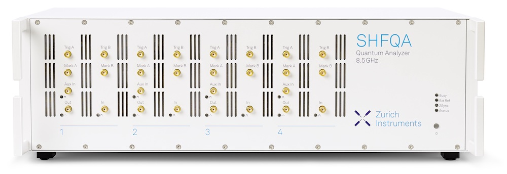 |
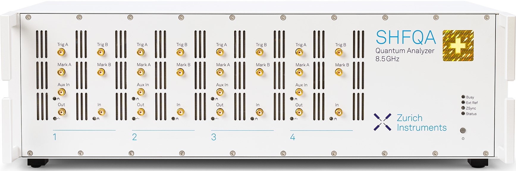 |
| Upgrading from SHFQA to SHFQA+ | Contact us to discuss the possibilities for your instruments! | - |