Synchronization of multiple HDAWGs
Note
This tutorial is applicable to the PQSC when used with multiple HDAWG.
Goals and Requirements
The goal of this tutorial is to demonstrate the multi-HDAWG synchronization with the PQSC. We demonstrate how to synchronize the clock reference of multiple HDAWG and how to synchronously start them. This tutorial assumes that you are already familiar with the HDAWG, otherwise, please do the tutorial ‘Basic Waveform Playback’ from the HDAWG user manual first. In order to visualize the multi-channel signals, an oscilloscope with sufficient bandwidth and channel number is required.
The equipment list is given below.
- 1 PQSC
- 2 or more HDAWGs
- 1 oscilloscope (min. 2 channels, recommended 4, bandwidth 500 MHz or more)
- 1 Ethernet switch
- 1 Ethernet cable per instrument (supplied with your PQSC and HDAWGs)
- 1 ZSync cable per HDAWG (supplied with your HDAWGs)
- 2 SMA coaxial cables
- 2 adaptors BNC male to SMA female
Preparation
Connect the cables as illustrated below. Make sure that the instruments are powered on and connected by Ethernet to your local area network (LAN) where the host computer resides.
For best performance, the system should be placed in a climate-controlled environment with stable temperature and humidity. Avoid exposing the instruments to direct sunlight.
After starting LabOne, the default web browser opens with the LabOne graphical user interface. It’s advised to open a tab in the browser for each instrument.

The tutorial can be started with the default instrument configuration (e.g. after a power cycle or after loading the Factory Default preset from the 'Device' tab) and the default user interface settings (e.g. as is after pressing F5 in the browser).
Note
The PQSC needs to warm up for 30 minutes after power-up. Do not lock to external reference clock or start triggering before it’s ready. The CLK LED on the bottom right of the LabOne user interface will turn green when the instrument is ready to use.
Multi device synchronization
The first step to enable the device synchronization is to enable the ZSync clock and triggers on the HDAWGs. The following table summarizes the necessary settings. It should be repeated for each HDAWG connected to the PQSC.
| Tab | Sub-tab | Section | # | Label | Setting / Value / State |
|---|---|---|---|---|---|
| Device | Configuration | Reference clock Source | ZSync | ||
| Device | Configuration | Sample Clock Frequency (Hz) | 2.4G | ||
| DIO | Digital I/O | Mode | QCCS |

After changing the selector, the ‘Status’ LED will turn yellow for few seconds and then green again to signal that the HDAWG successfully locked to the reference clock provided by the PQSC over ZSync.
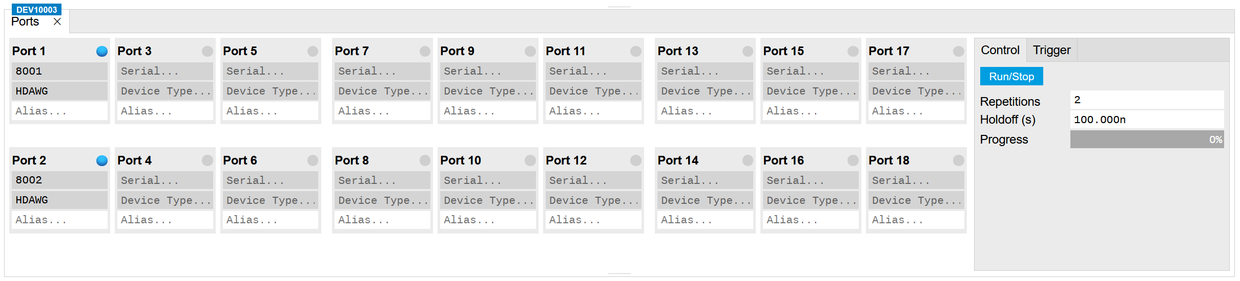
Then, check that the PQSC correctly recognized the HDAWGs. On the back of the instrument or in the ‘Ports’ tab of the PQSC verify that the status LED of the used ZSync ports turned blue and the serial number of the HDAWG is displayed. You may assign an alias to for each instrument to easily recognize it later.
The sample rate of the HDAWGs is variable. When used with the PQSC, two values are supported: 2.0 GSa/s or 2.4 GSa/s. The sample rate 2.0 GSa/s is useful when the HDAWG is used in conjunction with instruments from the SHF series which operate at the same sample rate. It’s not possible to mix the two sample rates: all HDAWGs connected to a PQSC must the same sample rate.
Multi device synchronous triggering
To have a synchronous start of the HDAWGs, the PQSC needs to generate start triggers over ZSync and the HDAWGs have to wait for them and then start the execution. In the HDAWGs, these signals are internally routed over the DIO interface, which will be unavailable for normal usage.
We configure the sequencers to play a square waveform as soon as the trigger from the PQSC is received. The necessary settings are summarized in the following table. This must be done for each HDAWG connected to the PQSC.
| Tab | Sub-tab | Section | # | Label | Setting / Value / State |
|---|---|---|---|---|---|
| Output | Waveform Generators | 4x2 channels | |||
| Output | Waveform Generators | 1 | Output Amplitude Wave 1 | 1.0 | |
| Output | Waveform Generators | 1 | Modulation | OFF | |
| Output | Wave Outputs | 1 | Range | 1 V | |
| Output | Wave Outputs | 1 | Enable | ON |
The following sequence should be loaded in the sequencer and then started:
wave w = ones(64);

while(true) {
  waitZSyncTrigger();
  playWave(w);
}
The AWG status LED will turn yellow, meaning that is ready and waiting for the trigger.
The scope should be configured as following:
| Scope Setting | Value / State |
|---|---|
| Ch1/Ch2 enable | ON |
| Ch1/Ch2 range | 0.2 V/div |
| Timebase | 20 ns/div |
| Trigger source | Ch1 |
| Trigger level | 200 mV |
| Run / Stop | ON |
Finally, we configure the periodic trigger generation in the Ports tab
of the PQSC and then start it by clinking on  button.
| Tab | Sub-tab | Section | # | Label | Setting / Value / State |
|---|---|---|---|---|---|
| Ports | Control | Repetitions | 2 | ||
| Ports | Control | Holdoff (s) | 100n |
On the scope we can now see two pulses with both channels aligned in time. The inter-channel alignment can be further adjusted by changing the delay of each HDAWG Wave output in the field "Output > Wave Outputs > Delay (s)". The two pulses are spaced by 100 ns as specified by the Holdoff time.
