Feedback Tab
The Feedback tab provides control and displays the flow of the feedback pipeline. It is available on all PQSC instruments.
Features
- Display the full feedback pipeline and how the elements are connected
- Control the register forwarding parameters
Description
| Control/Tool | Option/Range | Description |
|---|---|---|
| Feedback | Control and display of the feedback pipeline. |
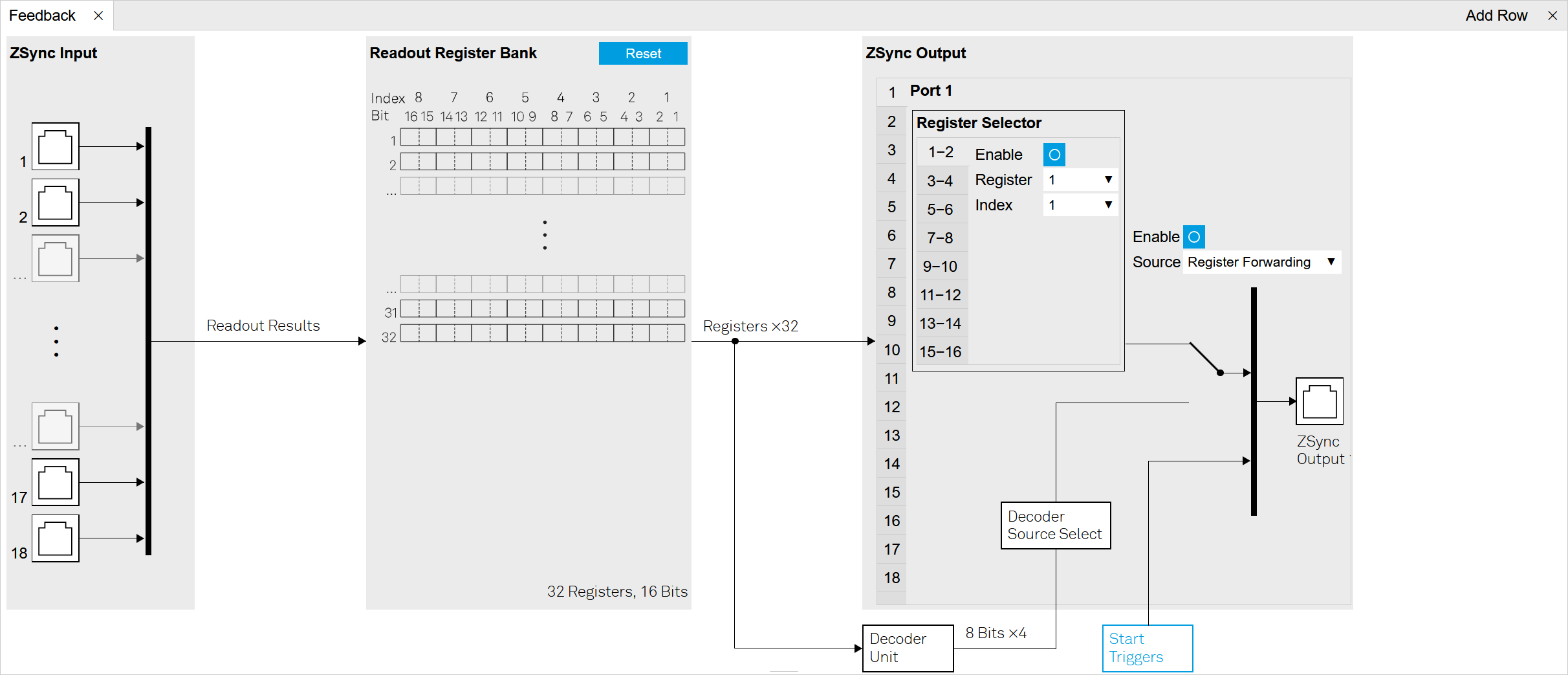
The Feedback tab (see LabOne UI: Feedback tab) shows the flow of data from the input ZSync ports on the left, to the output ZSync ports on the right. The readout register forwarding (see Register Forwarding for more details) can be configured from the output tab.
The PQSC provides a way to process readout result feedback actions in real time with minimal latency. Readout result are generated by the Quantum Analyzers, like the SHFQA, The QAChannel of the SHFQC or the UHFQA, while the feedback data are received by Signal Generators, like the SHFSG, the SGChannels of the SHFQC or the HDAWG. All the communications are done over ZSync.
The PQSC feedback architecture according to Figure 2 processes the incoming data in several stages. First, the incoming readout results are stored in the Readout Register Bank. The storage address is provided dynamically by the Quantum Analyzer. Then, a subset of the Readout Register Bank content can be forwarded directly to the signal generators or fed to a decoder for further processing.
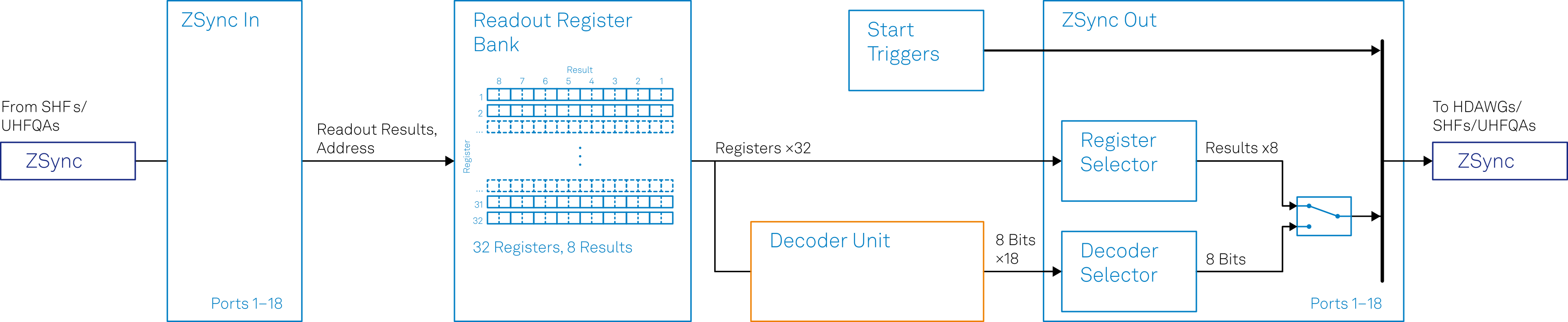
Readout Register Bank
The readout register bank is used to store multiple readout results measured by the Quantum Analyzers. The purpose of this memory is to provide a global point of access to all the last readouts done on multiple qubits. The register bank can be updated partially if not all the possible readouts are performed in a single cycle, for example if they are staggered. It’s possible to store multiple repeated measurements by using a different register for each readout cycle. The readout register bank is not intended to acquire the measurements for offline analysis and storage, but only for processing and feedback by the PQSC itself and the other connected instruments.
The Readout Register bank consists of 32 readout registers, of which each can store up to 16 qubit readout results from one QA readout channel (10 qubit readout results for the UHFQA). Every Quantum Analyzer connected to the PQSC writes into the readout register bank when it performs a readout. Only the qubits actually read are written into a register, the other bits are left untouched. The register address is specified in the sequencer by the Quantum Analyzer before the readout is started. Thus it can be changed between different readout events. From LabOne, the user can only clear all the registers before an experiment, the stored values are not accessible.
Register Forwarding
Readout register forwarding can be used to send a subset of the readout
register bank content to the signal generators without further
processing. Each ZSync output port can forward up to eight freely chosen
readout results, corresponding to up to sixteen qubit readouts or eight
qutrit/ququad readouts. Every port can be configured with its own set of
forwarded results. The forwarded results are specified by the register
number and index of the desired result inside of the register. Whenever
one of the linked registers is updated, its content is automatically
forwarded to the receiving instrument. This functionality is intended
for feedback which requires minimal latency and depends on the state of
very few qubits. The typical example is the active qubit/qutrit/ququad
reset, an initialization technique that relies on fast readout and
conditional reset. The forwarded results can be decoded on the receiving
instrument with the function getFeedback(ZSYNC_DATA_PROCESSED_A, ...)
or to immediately trigger a specific waveform play with
executeTableEntry(ZSYNC_DATA_PROCESSED_A, ...). Please refer to the
user manual of the receiving instrument for more details.
Decoders
Quantum error correction codes require to perform a syndrome measurement
to evaluate the eventual errors that corrupt the state of a set of
entangled qubits. Such measurement is performed by reading a subset of
the entangled qubits and from that deduce how to correct the error. This
evaluation is performed by the Decoder unit. This unit has access to the
whole readout register bank. It can generate an output as wide as one
byte per port. The decoder output can be read on the receiving
instrument with the function getFeedback(ZSYNC_DATA_PROCESSED_B) or
trigger immediately a specific waveform play with
executeTableEntry(ZSYNC_DATA_PROCESSED_B). Please refer to the user
manual of the receiving instrument for more details. The decoder is
implemented as a lookup table decoder.
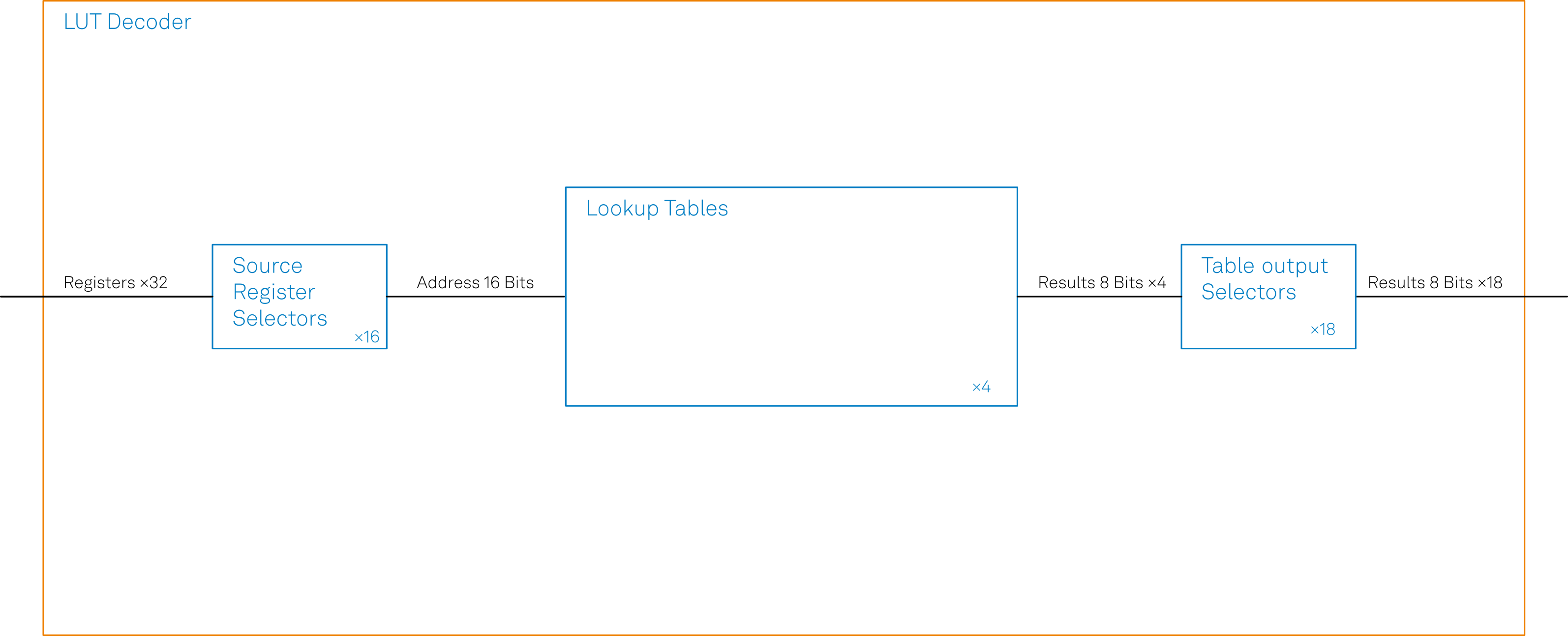
Lookup table decoder
The Lookup table decoder implement the error decoding function using lookup tables. In practice it’s a map of every possible input, also called address, to a list of outputs. It can be evaluated in a short and constant time. The Figure 3 shows the data flow. The Source register selector is used to reduce the large set of the readout registers to a word of 16 bits that serves as the input table address. Similarly to the the register forwarding feature, the user can select 16 sources register numbers and indices of the desired bit inside of each register. Then this address is used to access the 4 lookup tables. The tables are programmed with an array of 216 bytes. The input address will be used as index of the array. Each table will output 1 byte. Finally, for each ZSync output port, one of this 4 outputs is selected and forwarded to the receiving instrument. Whenever any of the readout results is updated, the lookup tables are evaluated and the outputs are sent together with a trigger event.
Note
The configuration of the Lookup table decoder is currently only accessible through the API.
Functional Elements
| Control/Tool | Option/Range | Description |
|---|---|---|
| Input Port | The input ZSync port where the QA instrument is connected. | |
| Readout Register Bank | The Readout Register Bank where the results coming from the QAs are stored. The destination coordinates are controlled by the QA sequencer. | |
| Reset | Clear all the readout registers. | |
| Enable | Enable feedback output for the current port. | |
| Source | Select the source of feedback data for the current port. | |
| Register Forwarding | Forward selected readout results to the given port. | |
| Decoder | Send the output of the Decoder unit to the given port. | |
| Output Port | The output ZSync port where triggers and feedback events are directed. | |
| Decoder Unit | The quantum error decoder unit. | |
| Start Triggers | The start synchronization triggers. | |
| Decoder Source Select | The source of the error decoder that is forwarded. | |
| Enable | Enable readout register forwarding of bits xx-yy to the current port. | |
| Register | The readout register to be forwarded. | |
| Index | The index of the results in the readout register to be forwarded. | |
| Bits | The pair of bits in the forwarded message. |