Extended register forwarding
Status until LabOne 23.02
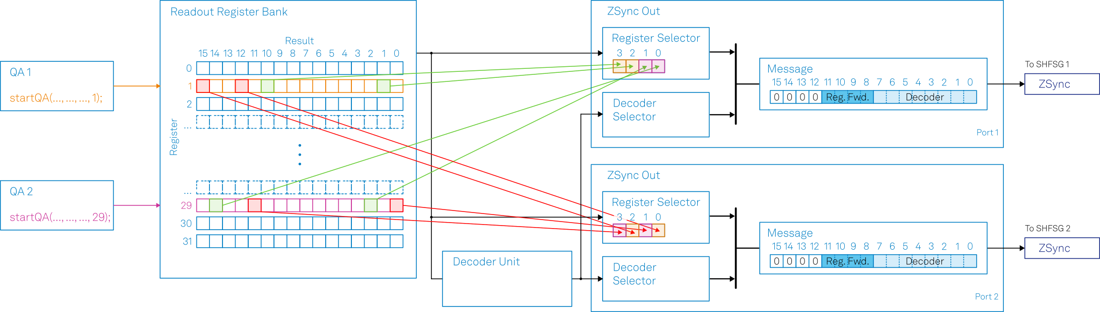
The PQSC has two feedback units: the register forwarding and the error decoder (see Feedback Tab for more details). The register forwarding unit is intended for simple feedback experiments, where a qubit readout maps directly to a feedback action, like active qubit reset. It can send up to four arbitrary qubit readout results per ZSync port, each one bit in size. Such results are selected from the readout register bank, a temporary storage of readout results populated by the QA units. The user can select the results to forward without constraint. This enable the system to perform a conditional action on a worker device, regardless of the origin of the readout. The number of results that can be forwarded is designed to match the capability of the instruments connected to the PQSC. Typically, an HDAWG8 is used to control up to four qubits, hence the choice of allowing the forwarding of four qubit readout results. The output of the register forwarding unit is multiplexed with the output of the error decoder unit and both are available for the worker instrument in the same message.
Example
In this example, there are two QA channels writing their readout results
in register 1 and 29 respectively. The PQSC is configured to forward
eight results to two different instruments connected to the first two
ZSync ports, as shown in Figure 1.
When a QA performs a readout, its results are automatically written in
the readout register specified in the fourth argument of the startQA
command, and the PQSC automatically forwards the chosen results.
To configure the PQSC as in Figure 1, its nodes should be programmed as in Table 1.
| Node | Value |
|---|---|
/DEV.../ZSYNCS/0/OUTPUT/REGISTERBANK/ENABLE |
True |
/DEV.../ZSYNCS/0/OUTPUT/REGISTERBANK/SOURCES/*/ENABLE |
True |
/DEV.../ZSYNCS/0/OUTPUT/REGISTERBANK/SOURCES/0/REGISTER |
29 |
/DEV.../ZSYNCS/0/OUTPUT/REGISTERBANK/SOURCES/0/INDEX |
14 |
/DEV.../ZSYNCS/0/OUTPUT/REGISTERBANK/SOURCES/1/REGISTER |
29 |
/DEV.../ZSYNCS/0/OUTPUT/REGISTERBANK/SOURCES/1/INDEX |
2 |
/DEV.../ZSYNCS/0/OUTPUT/REGISTERBANK/SOURCES/2/REGISTER |
1 |
/DEV.../ZSYNCS/0/OUTPUT/REGISTERBANK/SOURCES/2/INDEX |
1 |
/DEV.../ZSYNCS/0/OUTPUT/REGISTERBANK/SOURCES/3/REGISTER |
1 |
/DEV.../ZSYNCS/0/OUTPUT/REGISTERBANK/SOURCES/3/INDEX |
10 |
/DEV.../ZSYNCS/1/OUTPUT/REGISTERBANK/ENABLE |
True |
/DEV.../ZSYNCS/1/OUTPUT/REGISTERBANK/SOURCES/*/ENABLE |
True |
/DEV.../ZSYNCS/1/OUTPUT/REGISTERBANK/SOURCES/0/REGISTER |
1 |
/DEV.../ZSYNCS/1/OUTPUT/REGISTERBANK/SOURCES/0/INDEX |
12 |
/DEV.../ZSYNCS/1/OUTPUT/REGISTERBANK/SOURCES/1/REGISTER |
29 |
/DEV.../ZSYNCS/1/OUTPUT/REGISTERBANK/SOURCES/1/INDEX |
0 |
/DEV.../ZSYNCS/1/OUTPUT/REGISTERBANK/SOURCES/2/REGISTER |
1 |
/DEV.../ZSYNCS/1/OUTPUT/REGISTERBANK/SOURCES/2/INDEX |
15 |
/DEV.../ZSYNCS/1/OUTPUT/REGISTERBANK/SOURCES/3/REGISTER |
29 |
/DEV.../ZSYNCS/1/OUTPUT/REGISTERBANK/SOURCES/3/INDEX |
11 |
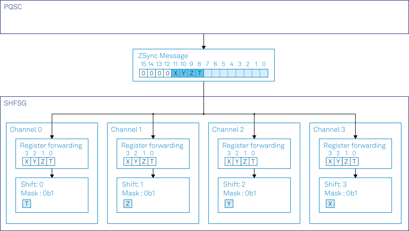
The instruments receive a word from the data sources configured in the
PQSC. Such words contain the output of both the register forwarding and
the error decoder unit. The conditional instruction, either
getFeedback or executeTableEntry, should specify the source of
feedback with the constant ZSYNC_DATA_PQSC_REGISTER or
ZSYNC_DATA_PQSC_DECODER to select the relevant portion of the message.
The constant ZSYNC_DATA_RAW provides the full message without any
processing. Each sequencer in the instrument can reduce the message to
the portion that is relevant for it; for example the state of a qubit to
reset. This is done by binary shift and masking. An optional additive
offset could be added. In Figure 2 an example of
the flow of data to reset four qubits connected to a SHFSG4 is provided.
In order to enable such processing, the instrument nodes should be configured as in Table 2.
| Node | Value |
|---|---|
/DEV.../SGCHANNELS/0/AWG/ZSYNC/REGISTER/SHIFT |
0 |
/DEV.../SGCHANNELS/0/AWG/ZSYNC/REGISTER/MASK |
0b1 |
/DEV.../SGCHANNELS/1/AWG/ZSYNC/REGISTER/SHIFT |
1 |
/DEV.../SGCHANNELS/1/AWG/ZSYNC/REGISTER/MASK |
0b1 |
/DEV.../SGCHANNELS/2/AWG/ZSYNC/REGISTER/SHIFT |
2 |
/DEV.../SGCHANNELS/2/AWG/ZSYNC/REGISTER/MASK |
0b1 |
/DEV.../SGCHANNELS/3/AWG/ZSYNC/REGISTER/SHIFT |
3 |
/DEV.../SGCHANNELS/3/AWG/ZSYNC/REGISTER/MASK |
0b1 |
With such settings, each sequencer can get its processed feedback in a
variable with var feedback = getFeedback(ZSYNC_DATA_PQSC_REGISTER) or
directly play a conditional pulse with
executeTableEntry(ZSYNC_DATA_PQSC_REGISTER).
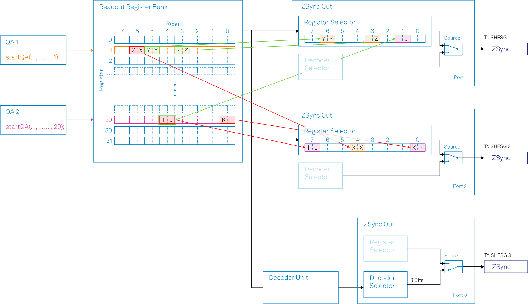
New behavior since LabOne 23.06
The register forwarding unit has been extended and it now supports forwarding of up to eight readout results, each made of up to two bits. This allows the system to perform active qubit/qutrit/ququad reset for each control channel on larger instruments like the SHFSG8 or SHFQC6. To enable that, three main aspects have been changed:
- The register forward selector picks couples of bits instead of single
bits. The index now refers to such couples and it’s equivalent to
2nbits. Allowed values are therefore from 0 to 7 instead of 0 to 15. - There are eight selectors instead of four.
- The data from the register forwarding unit and the decoder unit are not multiplexed anymore. Therefore a port can exclusively send data from register forwarding or the error decoder.
The nodes
/DEV.../ZSYNCS/n/OUTPUT/DECODER/ENABLE/DEV.../ZSYNCS/n/OUTPUT/REGISTERBANK/ENABLE
on the PQSC have been removed, and their functionality replaced by the nodes
/DEV.../ZSYNCS/n/OUTPUT/ENABLE/DEV.../ZSYNCS/n/OUTPUT/SOURCE
The ENABLE node is used to enable feedback output on a given port,
while the SOURCE node is used to select if a port should send data
from the register forwarding unit or from the decoder unit.
Example
Like in the previous example, there are two QA channels writing their readout results in register 1 and 29 respectively. QA1 is configured such that two results (X and Y) are the output of Multi State Discrimination (MSD), so each is composed by two bits, while another (Z) is the result of regular discrimination, so it uses only one bit. The QA2 produces three results (I,J and K) from regular discrimination, so a total of three bits. The PQSC is configured to forward these results to two different instruments connected to the first two ZSync ports, as shown in Figure 1. A third instrument is configured to receive the output of the decoder unit. For clarity in this example, the register forwarding is sending only three results per port instead of the maximum of eight and the configuration of the decoder unit is omitted.
To configure the PQSC as in Figure 3, its nodes should be programmed as in Table 3.
| Node | Value |
|---|---|
/DEV.../ZSYNCS/0/OUTPUT/ENABLE |
True |
/DEV.../ZSYNCS/0/OUTPUT/SOURCE |
"reg" |
/DEV.../ZSYNCS/0/OUTPUT/REGISTERBANK/SOURCES/1/ENABLE |
True |
/DEV.../ZSYNCS/0/OUTPUT/REGISTERBANK/SOURCES/1/REGISTER |
29 |
/DEV.../ZSYNCS/0/OUTPUT/REGISTERBANK/SOURCES/1/INDEX |
4 |
/DEV.../ZSYNCS/0/OUTPUT/REGISTERBANK/SOURCES/3/ENABLE |
True |
/DEV.../ZSYNCS/0/OUTPUT/REGISTERBANK/SOURCES/3/REGISTER |
1 |
/DEV.../ZSYNCS/0/OUTPUT/REGISTERBANK/SOURCES/3/INDEX |
3 |
/DEV.../ZSYNCS/0/OUTPUT/REGISTERBANK/SOURCES/6/ENABLE |
True |
/DEV.../ZSYNCS/0/OUTPUT/REGISTERBANK/SOURCES/6/REGISTER |
1 |
/DEV.../ZSYNCS/0/OUTPUT/REGISTERBANK/SOURCES/6/INDEX |
5 |
/DEV.../ZSYNCS/1/OUTPUT/ENABLE |
True |
/DEV.../ZSYNCS/1/OUTPUT/SOURCE |
"reg" |
/DEV.../ZSYNCS/1/OUTPUT/REGISTERBANK/SOURCES/0/ENABLE |
True |
/DEV.../ZSYNCS/1/OUTPUT/REGISTERBANK/SOURCES/0/REGISTER |
29 |
/DEV.../ZSYNCS/1/OUTPUT/REGISTERBANK/SOURCES/0/INDEX |
0 |
/DEV.../ZSYNCS/1/OUTPUT/REGISTERBANK/SOURCES/4/ENABLE |
True |
/DEV.../ZSYNCS/1/OUTPUT/REGISTERBANK/SOURCES/4/REGISTER |
1 |
/DEV.../ZSYNCS/1/OUTPUT/REGISTERBANK/SOURCES/4/INDEX |
6 |
/DEV.../ZSYNCS/1/OUTPUT/REGISTERBANK/SOURCES/7/ENABLE |
True |
/DEV.../ZSYNCS/1/OUTPUT/REGISTERBANK/SOURCES/7/REGISTER |
29 |
/DEV.../ZSYNCS/1/OUTPUT/REGISTERBANK/SOURCES/7/INDEX |
4 |
/DEV.../ZSYNCS/2/OUTPUT/ENABLE |
True |
/DEV.../ZSYNCS/2/OUTPUT/SOURCE |
"decoder" |
Like in the previous example, each sequencer in the instrument can reduce the message to the portion that is relevant for it by binary shift and masking. In Figure 4, there is an example of the flow of data of the SHFSG8 connected to the first ZSync port of the PQSC; it reset three qubits (channels 2 and 3) and one qutrit. Similarly, in Figure 5, the same goes for the SHFSG8 connected to the second ZSync port of the PQSC.
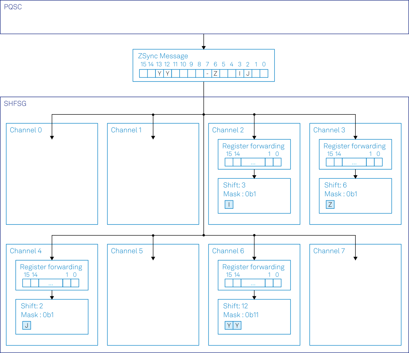
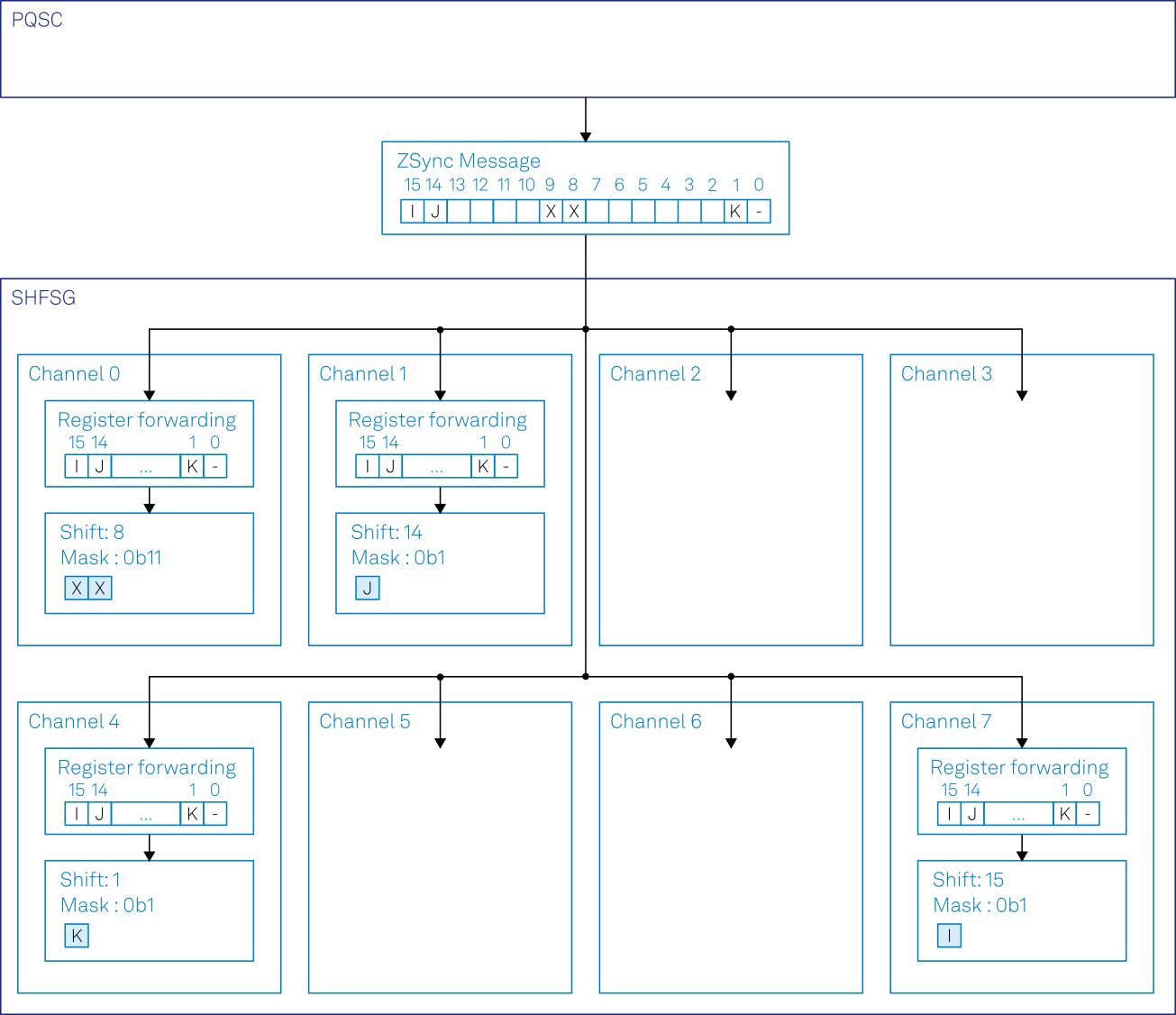
In order to enable such processing, the instrument nodes should be configured as in Table 4 and Table 5. It should be noted that the shift is still expressed in bits, not couples of bits like in the register selector of the PQSC. This allows for finer granularity in the selection of the interesting portion of the message. It also allows for the execution of feedback on a single bit, even if the PQSC register forwarding unit sent two bits, like in channel 2 and 3 of the first SHFSG.
| Node | Value |
|---|---|
/DEV.../SGCHANNELS/2/AWG/ZSYNC/REGISTER/SHIFT |
3 |
/DEV.../SGCHANNELS/2/AWG/ZSYNC/REGISTER/MASK |
0b1 |
/DEV.../SGCHANNELS/3/AWG/ZSYNC/REGISTER/SHIFT |
6 |
/DEV.../SGCHANNELS/3/AWG/ZSYNC/REGISTER/MASK |
0b1 |
/DEV.../SGCHANNELS/4/AWG/ZSYNC/REGISTER/SHIFT |
2 |
/DEV.../SGCHANNELS/4/AWG/ZSYNC/REGISTER/MASK |
0b1 |
/DEV.../SGCHANNELS/6/AWG/ZSYNC/REGISTER/SHIFT |
12 |
/DEV.../SGCHANNELS/6/AWG/ZSYNC/REGISTER/MASK |
0b11 |
above
| Node | Value |
|---|---|
/DEV.../SGCHANNELS/0/AWG/ZSYNC/REGISTER/SHIFT |
8 |
/DEV.../SGCHANNELS/0/AWG/ZSYNC/REGISTER/MASK |
0b11 |
/DEV.../SGCHANNELS/1/AWG/ZSYNC/REGISTER/SHIFT |
14 |
/DEV.../SGCHANNELS/1/AWG/ZSYNC/REGISTER/MASK |
0b1 |
/DEV.../SGCHANNELS/4/AWG/ZSYNC/REGISTER/SHIFT |
1 |
/DEV.../SGCHANNELS/4/AWG/ZSYNC/REGISTER/MASK |
0b1 |
/DEV.../SGCHANNELS/7/AWG/ZSYNC/REGISTER/SHIFT |
15 |
/DEV.../SGCHANNELS/7/AWG/ZSYNC/REGISTER/MASK |
0b1 |
above
Like before, the sequencers can acquire their feedback in a variable
with var feedback = getFeedback(ZSYNC_DATA_PQSC_REGISTER), or directly
play a conditional pulse with
executeTableEntry(ZSYNC_DATA_PQSC_REGISTER), so no changes there.