Functional Overview
This chapter provides the overview of the features provided by the SHFSG Instrument. nless explicitly stated otherwise, all contents of the manual apply to both the original SHFSG as well as the SHFSG+. The first section contains the description of the functional diagram and the hardware and software feature list. The next section details the front panel and the back panel of the measurement instrument. The following section provides product selection and ordering support.
Features
The SHFSG+ Instrument consists of several internal units that generate digital signals (light blue color, referred to as Digital Signal Units or DSUs) and several units that transform the digital signals into analog signals with the appropriate center frequency (dark blue color). The front panel is depicted on the left-hand side and the back panel is depicted on the right-hand side. The arrows between the panels and the interface units indicate selected physical connections and the data flow. The SHFSG+ 8.5 GHz Signal Generator comes in a 2-channel, 4-channel and an 8-channel variant, providing either 2,4 or 8 output channels, respectively. The ordering guide details the available upgrade options for each instrument type and whether the option can be upgraded directly in the field. The SHFSG2+ can be upgraded in the field to a SHFSG4+.

Each channel has signal generation (AWG, Modulation) functionality,
as well as common functionality such as the shared communications
(32-bit DIO, ZSync). The digital, complex-valued signal from the
Digital Signal Unit is up-converted to microwave frequencies in the analog
domain using the Signal Output Module.
Super-high-frequency Signal Outputs
- Low-noise SHF Outputs, DC - 8.5 GHz frequency range, 1 GHz modulation bandwidth
- Broadband double superheterodyne frequency upconversion
- Calibrated (Output) Power Range, selectable from -30 dBm to 10 dBm when using the RF path and from -30 dBm to 5 dBm when using the LF path
Advanced Pulse Sequencer
- Arbitrary Waveform Generator capability
- Advanced sequencing
- looping, branching
- command table
- advanced trigger control
- Digital modulation
Available Options
- SHFSG-RTR: Signals from up to 3 additional Digital Signal Units can be routed and added to any Output
Hardware Trigger Engine
- 1 Trigger Engine per Channel
- 1 Trigger Input per Channel
High-speed Connectivity
- SMA connectors on front and back panel for triggers, signals and external clock
- USB 3.0 high-speed host interface
- Maintenance USB connection
- LAN/Ethernet 1 Gbit/s controller interface
- DIO: 32-bit digital input-output port
- ZSync connector for clock synchronization and fast data transfer
- Clock input/output connectors (10 MHz)
Software Features
- Web-based, high-speed user interface with multi-instrument control
- Data server with multi-client support
- LabOne APIs, including Python, QCoDeS and Labber
- Turnkey software and firmware features for fast system tune-up
Front Panel Tour
The front panel SMA connectors and control LEDs are arranged as shown in Figure 2 and listed in Table 1.

| Position | Label / Name | Description |
|---|---|---|
| A | Trig | TTL Trigger Input |
| B | Mark | TTL Marker Output |
| C | Out | single-ended waveform Signal Output, DC-8.5 GHz, max. 10 dBm |
| D | Aux In | analog Auxiliary Input, max. 10 V |
| E | Aux In Over | unused |
| F | Output On |
|
| G | multicolor LEDs |
|
| Busy | unused | |
| Ext Ref |
|
|
| ZSync |
|
|
| Status |
|
|
| H |  Soft power button |
Power button with incorporated status LED
|
Back Panel Tour
The back panel is the main interface for power, control, service and connectivity to other ZI instruments. Please refer to Figure 3 and Table 2 for the detailed description of the items.

| Position | Label / Name | Description |
|---|---|---|
| A |  Earth ground |
4 mm banana jack connector for earth ground, electrically connected to the chassis and the earth pin of the power inlet |
| B | AC 100 - 240 V | Power inlet, fuse holder, and power switch |
| C | MDS 1 | Unused |
| D | MDS 2 | Unused |
| E | Maintenance | Maintenance USB port. Only for instrument maintenance, not for regular operation. Please use the USB port (see position H) instead. Some of the instruments have this port labeled as USB 1. |
| F | LAN 1GbE | 1 Gbit LAN connector for instrument control |
| G | DIO 32bit | 32-bit digital input/output (DIO) connector |
| H | USB | Universal Serial Bus (USB) 3.0 port for instrument control and data acquisition. Some of the instruments have this port labeled as USB 2. |
| I | ZSync Secondary | Unused Attention: This is not an Ethernet plug, connection to an Ethernet network might damage the Instrument. |
| J | ZSync Primary | Primary inter-instrument synchronization bus connector Attention: This is not an Ethernet plug, connection to an Ethernet network might damage the instrument. |
| K | External Clk In | External Reference Clock Input (10 MHz/100 MHz) for synchronization with other instruments |
| L | External Clk Out | External Reference Clock Output (10 MHz/100 MHz) for synchronization with other instruments |
Ordering Guide
Table 3 provides an overview of the available SHFSG+ products. Upgradeable features are options that can be purchased anytime without the need to send the Instrument back to Zurich Instruments.
| Product code | Product name | Description | Field upgrade possible |
|---|---|---|---|
| SHFSG2+ | SHFSG+ Signal Generator | Base 2-channel Super-High-Frequency Signal Generator (SHFSG+) | - |
| SHFSG4+ | SHFSG+ Signal Generator | Base 4-channel Super-High-Frequency Signal Generator (SHFSG+) | - |
| SHFSG8+ | SHFSG+ Signal Generator | Base 8-channel Super-High-Frequency Signal Generator (SHFSG+) | - |
| SHFSG-2T4 | SHFSG2+ to SHFSG4+ Upgrade Option | Software Upgrades the SHFSG2+ to a SHFSG4+ | yes |
| SHFSG-RTR | SHFSG Output Router and Adder Option | Option for all variants of the SHFSG+ and SHFSG | Yes |
| Feature | SHFSG2+ | SHFSG4+ | SHFSG8+ | SHFSGX+ + SHFSG-RTR |
|---|---|---|---|---|
| Number of Output Channels | 2 | 4 | 8 | 2 (SHFSG2+) 4 (SHFSG4+) 8 (SHFSG8+) |
| Number of analog RF synthesizers | 2 | 4 | 4 | 2 (SHFSG2+) 4 (SHFSG4+) 4 (SHFSG8+) |
| Mixer-calibration-free analog frequency upconversion (double super-heterodyne) |
yes | |||
| Frequency range | DC-8.5 GHz | |||
| Digital oscillators per channel | 8 | |||
| Digital signal units | 2 | 4 | 8 | 8 |
| Digital signal routing and adding | not applicable | not applicable | not applicable | up to 3 digital signals can be routed and added to any output channel |
| Total number of Markers/Triggers (1 each per channel) |
2/2 | 4/4 | 8/8 | 2/2 (SHFSG2+) 4/4 (SHFSG4+) 8/8 (SHFSG8+) |
| Vertical resolution Output | 14 bit | |||
| Digital IQ modulation | yes | |||
| ZSync capability | yes | |||
| Pulse-level Sequencing | yes | |||
| USB 3.0 | yes | |||
| LAN 1 Gbit/s | yes | |||
| Category | SHFSG | SHFSG+ |
|---|---|---|
| Description | Base instrument | Improved phase noise Improved output noise Fast output muting functionality |
| External differences | Base instrument | Holographic "+" sticker on front panel |
| Software differences | Base option set | "PLUS" option in option list |
| Product image | 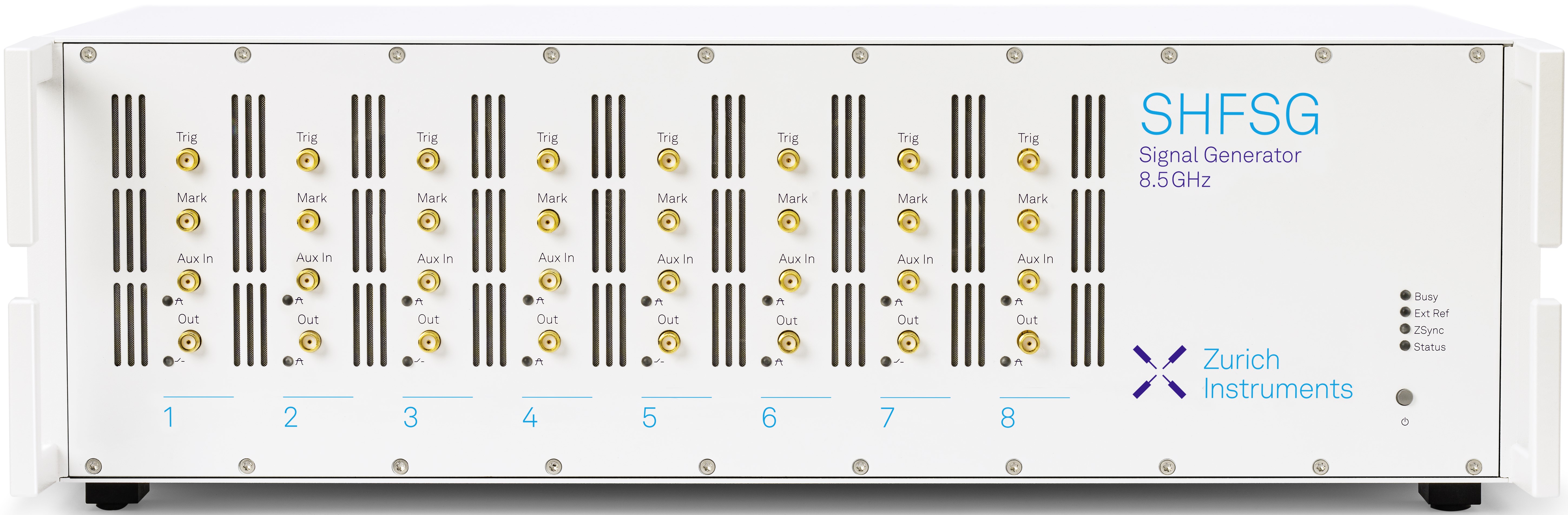 |
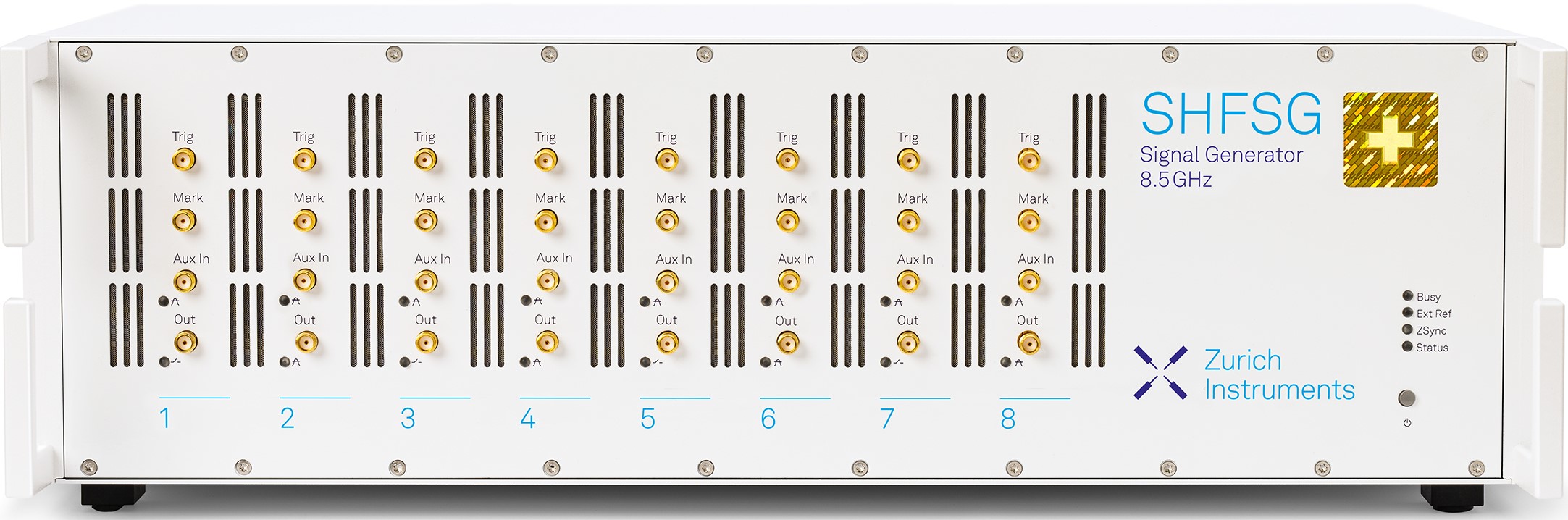 |
| Upgrading from SHFSG to SHFSG+ | Contact us to discuss the possibilities for your instruments! | - |