Output Tab
The Output tab can be used to configure the center frequency and maximum output power of the generated signals. It is available on all SHFSG+ instruments.
Features Overview
- Enable/disable output
- Define the Center Frequency of the modulation band
- Define the output power range
- Switch between Radio Frequency (RF) and Low Frequency (LF) paths
Description
| Control/Tool | Option/Range | Description |
|---|---|---|
| Output | Quick overview and access to all the settings for configuring the analog upconversion path. |
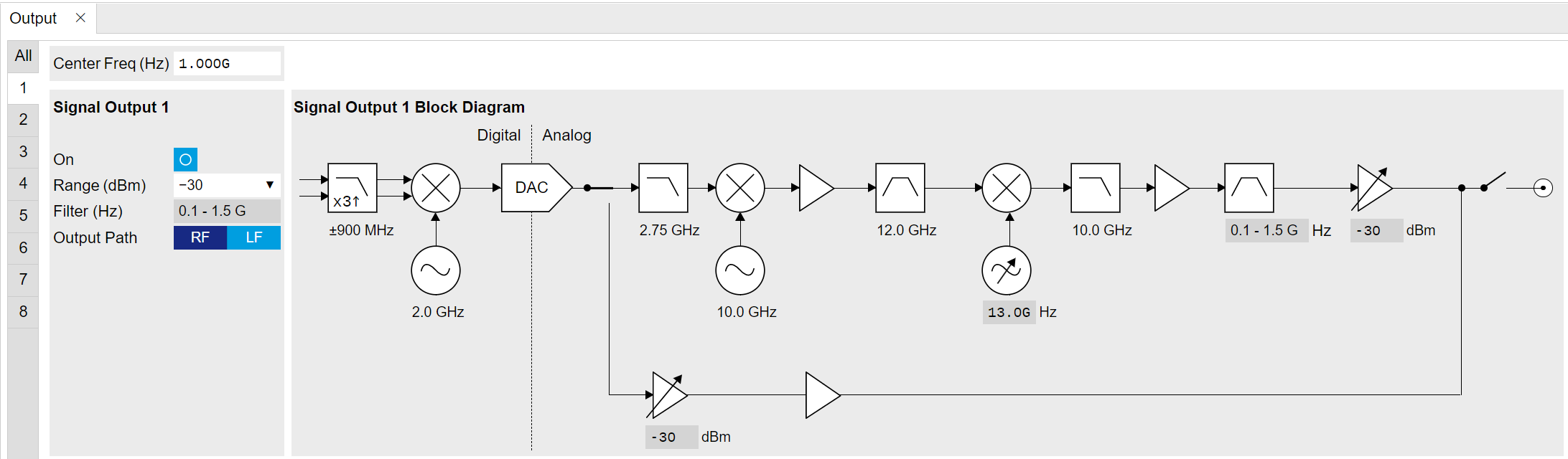
The SHFSG+ uses the double super-heterodyne frequency upconversion technique to generate its RF output frequencies, and each Signal Generator Channel has its own frequency upconversion chain. Each Signal Generator Channel has two available Output paths: the RF path for generating signals with center frequencies from 0.6 GHz to 8 GHz, and the LF path for generating signals with center frequencies from 0 GHz to 2 GHz. When using the RF path, center frequencies determine the frequency of an analog synthesizer and can be set with a resolution of 0.2 GHz. The SHFSG4+ and SHFSG8+ variants of the SHFSG+ contain 4 synthesizers, while the SHFSG2+ has 2. In the 2 and 4-channel variants, each Signal Generator Channel therefore has its own synthesizer, whereas in the 8-channel variant, there is 1 synthesizer per Signal Generator Channel pair. This means that Signal Generator Channels 1 and 2 must share the same RF center frequency in the 8-channel variant of the SHFSG+ Instrument when using the RF path. To achieve different output frequencies on Signal Generator Channels 1 and 2 in the 8-channel variant, digital modulation must be employed (see the Modulation Tab). When using the LF path, the center frequencies of each channel must be a multiple of 0.1 GHz and can be set independently of the other channels in all variants of the SHFSG+ Instrument.
Note
The LF and RF paths can be programmed with the same sequences (see the
Basic Waveform Playback Tutorial) but the LF path
has a shorter latency than the RF path due to the differences in the
analog part of the signal path. The differences in latencies can be
compensated by appropriate use of the playZero command, described in
the Tutorials.

When using the Signal Output of the RF path, the digital 1-GHz-wide modulation band centered around DC is first interpolated by a factor of 3, then digitally upconverted to 2 GHz (light blue elements) before it is passed to the 14-bit DAC. The resulting 2 GHz analog signal (dark blue elements) is then converted to 12 GHz by means of a local oscillator at 10 GHz. To remove all unwanted spurious signals, the signal is strongly filtered before it is down-converted in a second mixing process with a variable local oscillator. Depending on its software-controllable frequency value, the final output frequency band has a center frequency between 0.6-8 GHz and a width of ±0.5 GHz. Several amplifiers, attenuators, and filters in the up-conversion chain ensure that the different elements are not saturated and that the DAC range is faithfully mapped to the selected Output Range.
When using the LF path, the digital 1-GHz-wide modulation signal is still interpolated by a factor of 3 and passed to the 14-bit DAC, but the analog upconversion chain is bypassed. The center frequency is determined by setting the frequency of the oscillator used in the digital upconversion (fixed at 2 GHz when using the RF path, and can be set to a multiple of 100 MHz in the range 0 - 2 GHz when using the LF path). In this way, signals with center frequencies between 0 and 2 GHz can be generated with the LF path.
The advantages of this up-conversion scheme compared to IQ-mixer-based frequency conversion are that it is calibration-free, wide-band, and stable, in addition to having superior spurious tone performance. The optimal selection of the different gains, attenuators, and filters in the frequency conversion chains are taken over by the SHFSG+, such that only a few settings need to be set in the Output band parameters of the SHFSG+: Center Frequency, Output Range, and Output On.
Note
For both the LF and RF paths, the output power can be set in steps of 5 dBm, in the range -30 dBm to +10 dBm for the RF path and -30 dBm to +5 dBm for the LF path. If the power is set to a value that is outside this range or not a multiple of 5 dBm, the value will automatically be rounded to the nearest multiple of 5 dBm within the range for the path.
Note
It is highly recommended to enable all required inputs and outputs and wait for 2 hours after powering on the instrument.
Note
Please wait for at least 0.5 seconds after switching the center frequency or
power range before running a measurement. Alternatively, check the status of the node
/dev.../sgchannels/n/busy to be back at zero after a change.
Fast output muting
Note
Fast output muting is available only on the SHFSG+, not on the SHFSG. See Differences between SHFSG and SHFSG+
The SHFSG+ can dynamically mute the RF output in order to reduce the noise injected into the system under test when no signal is applied.
If the muting functionality is enabled, the marker output is connected to the attenuation elements that implement the ranging (see Figure 1). When the marker value is high, the range is lowered by 20 dB from the previously set value, and when it's low it's unchanged. The transition is fast and happens in few tens of nanoseconds, so it can be used in real-time sequences.
The marker output is functional even when muting is enabled. The signal is the same as the muting control and can't be changed.
Muting works only when the range is equal or higher than -10 dBm; if the range is lower, muting will have no effect, since the 20 dB attenuation used for muting is already enabled.
The muting functionality is offered by LabOneQ with the automute Calibration Option. When this option is active, LabOneQ will automatically turn on and off the mute depending on the signal generated.
Output Tab in the LabOne GUI
The Output settings can be accessed through the Output tab ![]() of the LabOne general user interface of the SHFSG+. After clicking on the tab,
an overview subtab opens that displays
all settings for all available Signal Generator Channels.
of the LabOne general user interface of the SHFSG+. After clicking on the tab,
an overview subtab opens that displays
all settings for all available Signal Generator Channels.
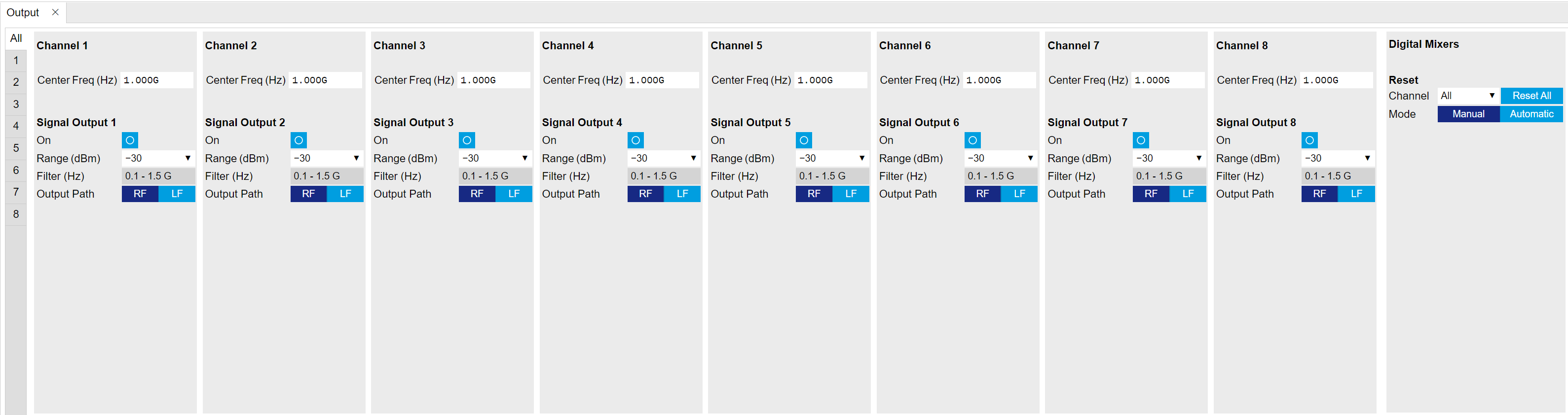
With the selectors at the left side of the Output tab, the detailed view of the up-conversion chain for the different Signal Generator Channels can be displayed. Each detailed view shows the available settings in the first, leftmost panel. In the second panel, a graphical representation of the currently selected parameters of the up-conversion chain is displayed.
Functional Elements
| Control/Tool | Option/Range | Description |
|---|---|---|
| Center Frequency | Center frequency of the output band at the output of the instrument. A copy of the displayed value is also contained in the read-only node '/{device}/sgchannels/{n}/centerfreq'. | |
| Center Frequency | Set center frequency of digital mixer. | |
| Output Digital Mixer Frequency | The Center Frequency of the digital mixer for the Signal Output. | |
| Center Frequency | Center frequency of the detection band at the input/output of the instrument. | |
| Variable Local Oscillator Frequency | This local oscillator converts between the fixed signal band around 12 GHz and the variable readout band at the In/Out connector. Shared between the Signal Input/Output modules of the same channel, its value is given by the user-determined Center Frequency value + 12 GHz. | |
| Input Digital Mixer Frequency | The Center Frequency of the digital mixer for the Signal Input. | |
| Variable Local Oscillator Frequency | This local oscillator converts between the fixed signal band around 12 GHz and the variable output band at the Out connector. Its value is given by the user-determined Center Frequency value + 12 GHz. | |
| Range | Maximal power at the input of the instrument. | |
| Input Path | RF path is used. | Switch between RF and LF input path. |
| LF path is used. | ||
| Range | Maximal power at the output of the instrument. | |
| Selectable RF Output Filter | The filter value is selected according to the Center Frequency value and ensures that higher signal harmonics are removed at the Signal Output. | |
| Output Path | RF path is used. | Switch between RF and LF output path. |
| LF path is used. | ||
| RF/LF Interlock | Enables the RF/LF path interlock between input and output. If enabled, the output path is always configured according to the input. | |
| Channel Select | Select which channel is to be cleared. | |
| Reset All | Reset all the channels. | |
| Reset Channel | Reset only the selected channel. | |
| Mode | Configure the NCO reset mode. |