Lock-in Tab
This tab is the main lock-in amplifier control panel. Users with instruments with SHFLI-MF Multi-frequency option installed are kindly referred to Lock-in Tab (SHF-MF option)
Features
- Parameter table with main input, output and demodulator controls
- Control elements for 8 configurable demodulators
- Control for 2 oscillators
- Settings for main signal inputs and signal outputs
Description
The Lock-in tab is the main control center of the instrument and open by default after start up.
Whenever the tab is closed or an additional one of the same type is needed, clicking the following icon will open a new instance of the tab.
| Control/Tool | Option/Range | Description |
|---|---|---|
| Lock-in | Quick overview and access to all the settings and properties for signal generation and demodulation. |
The Lock-in tab provides controls for all demodulators in the instrument.
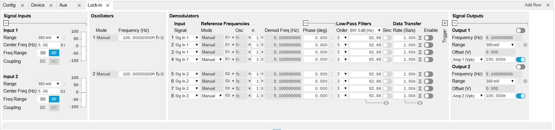
The Lock-in tab (see Figure 1) consists of 4 vertical sections: Signal Inputs, Oscillators, Demodulators and Signal Outputs. The Demodulator section is divided horizontally into two identical groups. The upper group is tied to oscillator 1 (f1) and channel 1 (c1), while the lower group is tied to oscillator 2 (f2) and channel 2 (c2). That means demodulators 1 to 4 (5 to 8) demodulate the signals from input 1 (2) at the center frequency of channel 1 (2), plus the frequency of oscillator 1 (2) times a multiplier n. Signal Input 1 and 2 are identical in all aspects, the same holds for the Signal Outputs 1 and 2, but each channel has its own independent center frequency.
The Signal Inputs section allows the user to define all settings relevant to the signal at the input such as input coupling, amplitude range, etc. On the right-hand side of the Lock-in tab the Signal Outputs section allows defining signal amplitudes and range values for the generated sinusoidal signal.
The "Freq Range" button toggles the input between baseband, in which no analog mixing occurs and the signal is digitized directly, and RF, in which the analog up- and down-mixing path is selected. The AC/DC button sets the coupling type: AC coupling has a high-pass cutoff frequency that can be used to block large DC signal components to prevent input signal saturation during amplification. This button is only active when in baseband (BB) mode, because RF mode is AC coupled by design.
The Oscillator section controls the frequencies of both internal oscillators. When the Mode indicator shows Manual, the user can define the oscillator frequency manually by typing a frequency value in the field.
We now discuss the Demodulators settings in more detail. The block diagram displayed in Figure 2 shows the main demodulator components and their interconnection. The understanding of the wiring is essential for successfully operating the instrument.

Every line in the Demodulators section represents one demodulator and all 4 demodulators in each group can be used to demodulate simultaneously the signal from their signal input, using different filter settings or at different harmonic frequencies of their oscillator within the channel’s measurement window. Demodulation of frequencies that are at integer multiples of any of the oscillator frequencies is achieved by entering the desired factor in the "n" column; the demodulation frequency is then the oscillator frequency times the factor n plus the channel center frequency. The result of the demodulation, the amplitude and phase can be read, for instance, using the Numeric tab which is described in Numeric Tab.
In the center of the Lock-in tab is the Low-Pass Filters section where the filter order for each demodulator can be selected in the drop-down list and the filter bandwidth (BW 3dB) can be chosen by typing a numerical value. Alternatively, the time constant of the filter (TC) or the noise equivalent power filter bandwidth (BW NEP) can be chosen from the drop-down menu in the column’s header. Each unit of the filter order correspond to a 6 dB/oct increase in the filter steepness; for example, setting the filter order to 4 corresponds to a roll off of 24 dB/oct or 80 dB/dec i.e. an attenuation of 104 for a tenfold frequency increase. If the Low-Pass Filter bandwidth is comparable to, or larger than the oscillator frequency (not the full demodulator frequency), the demodulator output may contain frequency components at the frequency of demodulation and its higher harmonics, when operating in baseband, or the component at the center of the measurement window (i.e. oscillator frequency =0). In this case, a smaller low-pass filter bandwidth is recommended, and the additional Sinc Filter should be enabled. The Sinc Filter is useful when measuring at low oscillator frequencies, since it allows one to apply a Low-Pass Filter bandwidth closer to the oscillator frequency, thus speeding up the measurement time.
The transfer of demodulator output data is activated with the Enable button in the Data Transfer section where also the sampling rate (Rate) for each demodulator can be defined.
In the Signal Outputs section the On buttons are used to activate the Signal Outputs and remain available even when the Signal Outputs panel is collapsed. This is also the place where the output amplitudes for each of the Signal Outputs can be set in adjustable units (Vpk or Vrms). The Range drop-down list is used to select the proper output range setting. When in the baseband (BB) mode, a DC offset can be applied to the output signal. Moreover, the harmonic and phase of the output signal can be adjusted here.
Functional Elements
Note
Please note that some elements will be implemented in a future LabOne release. This is reflected in the description of these elements in the table below and also in the LabOne tooltips.
| Control/Tool | Option/Range | Description |
|---|---|---|
| Frequency Range | Switch between RF and Baseband frequency range. | |
| Center Frequency | Center frequency of the detection band at the input/output of the instrument. | |
| Range | Defines the gain of the analog input amplifier. The range should exceed the incoming signal by roughly a factor two including a potential DC offset. The instrument selects the next higher available range relative to a value inserted by the user. A suitable choice of this setting optimizes the accuracy and signal-to-noise ratio by ensuring that the full dynamic range of the input ADC is used. |
|
| Auto |  |
Automatic adjustment of the Range to about two times the maximum signal input amplitude measured over about 100 ms. It will be implemented in a future release. |
| Coupling | OFF: DC coupling | Defines the input coupling for the Signal Inputs. AC coupling inserts a high-pass filter. |
| ON: AC coupling | ||
| Mode | Indicates how the frequency of the corresponding oscillator is controlled (manual, external reference, PLL, PID). Read only flag. | |
| Manual | The user setting defines the oscillator frequency. | |
| ExtRef | An external reference is mapped onto the oscillator frequency. | |
| Frequency (Hz) | Frequency control for each oscillator. | |
| Locked | ON / OFF | Oscillator locked to external reference when turned on. |
| Mode | Select the reference mode (manual or external reference) or indicate the unit that uses the demodulator (e.g. PLL). | |
| Manual | Default lock-in operating mode with manually set reference frequency. | |
| ExtRef | The demodulator is used for external reference mode and tracks the frequency of the selected reference input. The demodulator bandwidth is set automatically to adapt to the signal properties. | |
| Osc | oscillator index | Connects the selected oscillator with the demodulator corresponding to this line. Number of available oscillators depends on the installed options. |
| n | 1 to 1023 | Multiplies the demodulator's reference frequency with the integer factor defined by this field. |
| Demod Freq (Hz) | Indicates the frequency used for demodulation and for output generation. | |
| Phase (deg) | -180° to 180° | Phase shift applied to the reference input of the demodulator. |
| Zero |  |
Adjust the phase of the demodulator reference automatically in order to read zero degrees at the demodulator output. This action maximizes the X output, zeros the Y output, zeros the Θ output, and leaves the R output unchanged. |
| Signal | Selects the signal source to be associated to the demodulator. | |
| Sig In 2 | Signal Input 2 is connected to the corresponding demodulator. | |
| Sig In 1 | Signal Input 1 is connected to the corresponding demodulator. | |
| Order | Selects the filter roll off between 6 dB/oct and 48 dB/oct. | |
| 1 | 1st order filter 6 dB/oct | |
| 2 | 2nd order filter 12 dB/oct | |
| 3 | 3rd order filter 18 dB/oct | |
| 4 | 4th order filter 24 dB/oct | |
| TC/BW Select | Defines the display unit of the low-pass filters: time constant (TC) in seconds, noise equivalent power bandwidth (BW NEP) in Hz, 3 dB bandwidth (BW 3 dB) in Hz. | |
| TC | Defines the low-pass filter characteristic using time constant (s) of the filter. | |
| BW NEP | Defines the low-pass filter characteristic using the noise equivalent power bandwidth (Hz) of the filter. | |
| BW 3 dB | Defines the low-pass filter characteristic using the 3 dB cut-off frequency (Hz) of the filter. | |
| TC/BW Value | numeric value | Defines the low-pass filter characteristic in the unit defined above. |
| Sinc | ON / OFF | Enables the sinc filter. When the filter bandwidth is comparable to or larger than the demodulation frequency, the demodulator output may contain frequency components at the frequency of demodulation and its higher harmonics. The sinc is an additional filter that attenuates these unwanted components in the demodulator output. |
| Filter Lock |  |
Makes all demodulator filter settings equal (order, time constant, bandwidth). Enabling the lock copies the settings from demodulator 1 to all other demodulators. With locked filters, any modification to a filter setting is applied to all other filters, too. Releasing the lock does not change any setting. |
| Enable Streaming | ON / OFF | Enables the data acquisition and streaming of demodulated samples to the host computer for the corresponding demodulator. The streaming rate is defined in the field on the right hand side. Enabling a stream activates a corresponding element in the numeric tab and allows for demodulated samples to be visualized and analyzed in any of the LabOne measurement tools. Note: increasing number of active demodulators increases load on physical connection to the host computer. |
| Rate (Sa/s) | Defines the demodulator sampling rate, the number of samples that are sent to the host computer per second. A rate of about 7-10 higher as compared to the filter bandwidth usually provides sufficient aliasing suppression. This is also the rate of data received by LabOne Data Server and saved to the computer hard disk. This setting has no impact on the sample rate on the auxiliary outputs connectors. Note: the value inserted by the user may be approximated to the nearest value supported by the instrument. |
|
| Demodulator Sampling Rate Lock | |
Makes all demodulator sampling rates equal. Enabling the lock copies the settings from demodulator 1 to all other demodulators. With locked sampling rates, any modification to a sampling rate is applied to all other sampling rate fields, too. Releasing the lock does not change any setting. |
| Amplitude Unit | Vpk, Vrms | Select the unit of the displayed amplitude value. |
| Amplitude Enable | ON / OFF | Enables individual output signal amplitude. |
| Auto Range | |
Selects the most suited output range automatically. It will be implemented in a future release. |
| Output Clipping | grey/red | Indicates that the specified output amplitude(s) exceeds the range setting. Signal clipping occurs and the output signal quality is degraded. Adjustment of the range or the output amplitudes is required. |
| Offset | -range to range | Defines the DC voltage that is added to the dynamic part of the output signal. |
| On | ON / OFF | Main switch for the Signal Output corresponding to the blue LED indicator on the instrument front panel. |
| Range | Defines the maximum output voltage that is generated by the corresponding Signal Output. This includes the potential multiple Signal Amplitudes and Offsets summed up. Select the smallest range possible to optimize signal quality. This setting ensures that no levels or peaks above the setting are generated, and therefore it limits the values that can be entered as output amplitudes. Therefore selected output amplitudes are clipped to the defined range and the clipping indicator turns on. If 50 Ω target source or differential output is enabled the possible maximal output range will be half. |
|
| Amp 1/2 | -range to range | Defines the output amplitude for each demodulator frequency as rms or peak-to-peak value. A negative amplitude value is equivalent to a phase change of 180 degree. Demodulator 4 is the signal source for Signal Output 1, demodulator 8 is the source for Signal Output 2. |