Device Node Tree
This chapter contains reference documentation for the settings and measurement data available on SHFPPC Instruments. Whilst other chapters in this manual describes many of these settings in terms of the features available in the LabOne User Interface, this chapter describes them on the device level and provides a hierarchically organized and comprehensive list of device functionality.
Since these settings and data streams may be written and read using the LabOne APIs (Application Programming Interfaces) this chapter is of particular interest to users who would like to perform measurements programmatically via LabVIEW, Python, MATLAB, .NET or C.
Please see:
- Introduction for an introduction of how the instrument's settings and measurement data are organized hierarchically in the Data Server's so-called "Node Tree".
- Reference Node Documentation for a reference list of the settings and measurement data available on SHFPPC Instruments, organized by branch in the Node Tree.
Introduction
This chapter provides an overview of how an instrument's configuration and output is organized by the Data Server.
All communication with an instrument occurs via the Data Server program the instrument is connected to (see LabOne Software Architecture for an overview of LabOne's software components). Although the instrument's settings are stored locally on the device, it is the Data Server's task to ensure it maintains the values of the current settings and makes these settings (and any subscribed data) available to all its current clients. A client may be the LabOne User Interface or a user's own program implemented using one of the LabOne Application Programming Interfaces, e.g., Python.
The instrument's settings and data are organized by the Data Server in a file-system-like hierarchical structure called the node tree. When an instrument is connected to a Data Server, its device ID becomes a top-level branch in the Data Server's node tree. The features of the instrument are organized as branches underneath the top-level device branch and the individual instrument settings are leaves of these branches.
For example, the auxiliary outputs of the instrument with device ID "dev1000" are located in the tree in the branch:
/dev1000/auxouts/
In turn, each individual auxiliary output channel has its own branch underneath the "AUXOUTS" branch.
/dev1000/auxouts/0/
/dev1000/auxouts/1/
/dev1000/auxouts/2/
/dev1000/auxouts/3/
Whilst the auxiliary outputs and other channels are labelled on the instrument's panels and the User Interface using 1-based indexing, the Data Server's node tree uses 0-based indexing. Individual settings (and data) of an auxiliary output are available as leaves underneath the corresponding channel's branch:
/dev1000/auxouts/0/demodselect
/dev1000/auxouts/0/limitlower
/dev1000/auxouts/0/limitupper
/dev1000/auxouts/0/offset
/dev1000/auxouts/0/outputselect
/dev1000/auxouts/0/preoffset
/dev1000/auxouts/0/scale
/dev1000/auxouts/0/value
These are all individual node paths in the node tree; the lowest-level nodes which represent a single instrument setting or data stream. Whether the node is an instrument setting or data-stream and which type of data it contains or provides is well-defined and documented on a per-node basis in the Reference Node Documentation section in the relevant instrument-specific user manual. The different properties and types are explained in Node Properties and Data Types .
For instrument settings, a Data Server client modifies the node's value by specifying the appropriate path and a value to the Data Server as a (path, value) pair. When an instrument's setting is changed in the LabOne User Interface, the path and the value of the node that was changed are displayed in the Status Bar in the bottom of the Window. This is described in more detail in Exploring the Node Tree.
Module Parameters
LabOne Core Modules, such as the Sweeper, also use a similar tree-like structure to organize their parameters. Please note, however, that module nodes are not visible in the Data Server's node tree; they are local to the instance of the module created in a LabOne client and are not synchronized between clients.
Node Properties and Data Types
A node may have one or more of the following properties:
| Property | Description |
|---|---|
| Read | Data can be read from the node. |
| Write | Data can be written to the node. |
| Setting | The node corresponds to a writable instrument configuration. The data of these nodes are persisted in snapshots of the instrument and stored in the LabOne XML settings files. |
| Streaming | A node with the read attribute that provides instrument data, typically at a user-configured rate. The data is usually a more complex data type, for example demodulator data is returned as ZIDemodSample. A full list of streaming nodes is available in the Programming Manual in the Chapter Instrument Communication. Their availability depends on the device class (e.g. MF) and the option set installed on the device. |
| Pipelined | If the sequence pipeliner mode is off the value set to the node is applied immediately. Otherwise, it goes to the staging area of the sequence pipeliner instead. Multiple pipelined nodes can be programmed as part of a job definition, that is finalized by writing a one to the relevant commit node. |
A node may contain data of the following types:
| Type | Description |
|---|---|
| Integer | Integer data. |
| Double | Double precision floating point data. |
| String | A string array. |
| Integer (enumerated) | As for Integer, but the node only allows certain values. |
| Composite data type | For example, ZIDemodSample. These custom data types are structures whose fields contain the instrument output, a timestamp and other relevant instrument settings such as the demodulator oscillator frequency. Documentation of custom data types is available in |
Exploring the Node Tree
In the LabOne User Interface
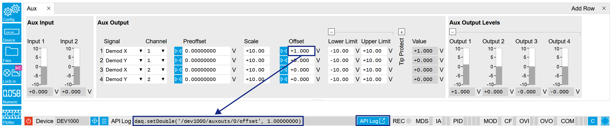
A convenient method to learn which node is responsible for a specific instrument setting is to check the Command Log history in the bottom of the LabOne User Interface. The command in the Status Bar gets updated every time a configuration change is made. Figure 1 shows how the equivalent MATLAB command is displayed after modifying the value of the auxiliary output 1's offset. The format of the LabOne UI's command history can be configured in the "Config" tab of LabOne User Interface. The commands can be displayed in MATLAB, Python and .NET programming languages. The entire history generated in the current UI session can be viewed by clicking the "API Log" button.
In a LabOne Programming Interface
A list of nodes (under a specific branch) can be requested from the Data
Server in an API client using the listNodes command (MATLAB, Python,
.NET) or ziAPIListNodes() function (C API). Please see each API's
command reference for more help using the listNodes command. To obtain
a list of all the nodes that provide data from an instrument at a high
rate, so-called streaming nodes, the streamingonly flag can be
provided to listNodes. More information on data streaming and
streaming nodes is available in the LabOne Programming Manual.
The detailed descriptions of nodes that is provided in
Reference Node Documentation is accessible directly in the LabOne MATLAB or Python
programming interfaces using the "help" command. The help command is
daq.help(path) in Python and ziDAQ('help', path) in MATLAB. The
command returns a description of the instrument node including access
properties, data type, units and available options. The "help" command
also handles wildcards to return a detailed description of all nodes
matching the path. An example is provided below.
    daq = zhinst.core.ziDAQServer('localhost', 8004, 6)
    daq.help('/dev1000/auxouts/0/offset')
    # Out:
    # /dev1000/auxouts/0/OFFSET#
    # Add the specified offset voltage to the signal after scaling. Auxiliary Output
    # Value = (Signal+Preoffset)*Scale + Offset
    # Properties: Read, Write, Setting
    # Type: Double
    # Unit: V
Data Server Nodes
The Data Server has nodes in the node tree available under the top-level
/zi/ branch. These nodes give information about the version and state of
the Data Server the client is connected to. For example, the nodes:
/zi/about/version/zi/about/revision
are read-only nodes that contain information about the release version
and revision of the Data Server. The nodes under the /zi/devices/ list
which devices are connected, discoverable and visible to the Data
Server.
The nodes:
/zi/config/open/zi/config/port
are settings nodes that can be used to configure which port the Data Server listens to for incoming client connections and whether it may accept connections from clients on hosts other than the localhost.
Nodes that are of particular use to programmers are:
/zi/debug/logpath- the location of the Data Server's log in the PC's file system,/zi/debug/level- the current log-level of the Data Server (configurable; has the Write attribute),/zi/debug/log- the last Data Server log entries as a string array.
The Global nodes of the LabOne Data Server are listed in the LabOne API User Manual.
Reference Node Documentation
This section describes all the nodes in the data server’s node tree organized by branch.
CLOCKBASE
/dev..../clockbase 
| Properties: | Read |
| Type: | Double |
| Unit: | Hz |
Returns the internal clock frequency of the device.
FEATURES
PPCHANNELS
/dev..../ppchannels/n/cancellation/attenuation 
| Properties: | Read, Write, Setting |
| Type: | Double |
| Unit: | dB |
Sets the attenuation applied to the cancellation tone.
/dev..../ppchannels/n/cancellation/on 
| Properties: | Read, Write, Setting |
| Type: | Integer (64 bit) |
| Unit: | None |
Enables pump tone cancellation.
/dev..../ppchannels/n/cancellation/phaseshift 
| Properties: | Read, Write, Setting |
| Type: | Double |
| Unit: | deg |
Sets the phase shift applied to the cancellation tone.
/dev..../ppchannels/n/cancellation/signalpower 
| Properties: | Read |
| Type: | Double |
| Unit: | dBm |
Total signal power after cancellation. Provides an indication of how well the pump tone has been suppressed. This value is read-only.
/dev..../ppchannels/n/cancellation/source 
| Properties: | Read, Write, Setting |
| Type: | Integer (enumerated) |
| Unit: | None |
Selects the source for the cancellation tone.
| 0 | "internal": Self-generated pump tone via internal loop-back. |
| 1 | "external": External pump tone via the PUMP IN connector. |
/dev..../ppchannels/n/cancellation/sourcefreq 
| Properties: | Read, Write, Setting |
| Type: | Double |
| Unit: | Hz |
Sets the frequency of the externally sourced cancellation tone. This value is locked to the self-generated pump tone frequency when internal loop-back is enabled.
/dev..../ppchannels/n/synthesizer/probe/freq 
| Properties: | Read, Write, Setting |
| Type: | Double |
| Unit: | Hz |
Sets the frequency of the generated probe tone.
/dev..../ppchannels/n/synthesizer/probe/maxpower 
| Properties: | Read |
| Type: | Double |
| Unit: | dBm |
Maximum probe tone power the instrument can provide at current operation point (depends on channel's pump tone settings, and probe tone frequency). This value is read-only.
/dev..../ppchannels/n/synthesizer/probe/minpower 
| Properties: | Read |
| Type: | Double |
| Unit: | dBm |
Minimum probe tone power the instrument can provide at current operation point (depends on channel's pump tone settings, and probe tone frequency). This value is read-only.
/dev..../ppchannels/n/synthesizer/probe/on 
| Properties: | Read, Write, Setting |
| Type: | Integer (64 bit) |
| Unit: | None |
Enables probe tone output.
/dev..../ppchannels/n/synthesizer/probe/power 
| Properties: | Read, Write, Setting |
| Type: | Double |
| Unit: | dBm |
Sets the output power of the generated probe tone.
/dev..../ppchannels/n/synthesizer/pump/alc 
| Properties: | Read, Write, Setting |
| Type: | Integer (64 bit) |
| Unit: | None |
Enables automatic level control (ALC) for pump tone output.
/dev..../ppchannels/n/synthesizer/pump/filter 
| Properties: | Read, Write, Setting |
| Type: | Integer (64 bit) |
| Unit: | None |
Enables the integrated low-pass filter on the pump tone signal path. Filter cut-off frequency is automatically adjusted based on pump tone frequency.
/dev..../ppchannels/n/synthesizer/pump/freq 
| Properties: | Read, Write, Setting |
| Type: | Double |
| Unit: | Hz |
Sets the frequency of the generated pump tone.
/dev..../ppchannels/n/synthesizer/pump/maxpower 
| Properties: | Read |
| Type: | Double |
| Unit: | dBm |
Maximum pump tone power the instrument can provide at current operation point (depends on ALC mode, low-pass filter mode, power range setting, and frequency). This value is read-only.
/dev..../ppchannels/n/synthesizer/pump/minpower 
| Properties: | Read |
| Type: | Double |
| Unit: | dBm |
Minimum pump tone power the instrument can provide at current operation point (depends on ALC mode, low-pass filter mode, power range setting, and frequency). This value is read-only.
/dev..../ppchannels/n/synthesizer/pump/on 
| Properties: | Read, Write, Setting |
| Type: | Integer (64 bit) |
| Unit: | None |
Enables pump tone output.
/dev..../ppchannels/n/synthesizer/pump/power 
| Properties: | Read, Write, Setting |
| Type: | Double |
| Unit: | dBm |
Sets the output power of the generated pump tone.
/dev..../ppchannels/n/synthesizer/pump/range 
| Properties: | Read, Write, Setting |
| Type: | Integer (enumerated) |
| Unit: | None |
Sets the channel's RF synthesizer output power range mode. A precise indication of the instrument's power limits in the individual modes is available by query of the MAXPOWER and MINPOWER nodes.
| 0 | "autorange": AUTO: The instrument automatically selects the range based on requested pump tone power. |
| 1 | "lowrange": LOW: The instrument is configured for lower power output. |
| 2 | "highrange": HIGH: The instrument is configured for higher power output. |
/dev..../ppchannels/n/synthesizer/status 
| Properties: | Read |
| Type: | Integer (enumerated) |
| Unit: | None |
Current operational mode of the channel's RF synthesizer board. This value is read-only.
| 0 | "pump": Synthesizer is configured for pump tone output. |
| 1 | "probe": Synthesizer is providing a probe tone to the adjacent channel. |
STATS
/dev..../stats/cmdstream/bandwidth 
| Properties: | Read |
| Type: | Double |
| Unit: | Mbit/s |
Command streaming bandwidth usage on the physical network connection between device and data server.
/dev..../stats/cmdstream/bytesreceived 
| Properties: | Read |
| Type: | Integer (64 bit) |
| Unit: | B |
Number of bytes received on the command stream from the device since session start.
/dev..../stats/cmdstream/bytessent 
| Properties: | Read |
| Type: | Integer (64 bit) |
| Unit: | B |
Number of bytes sent on the command stream from the device since session start.
/dev..../stats/cmdstream/packetslost 
| Properties: | Read |
| Type: | Integer (64 bit) |
| Unit: | None |
Number of command packets lost since device start. Command packets contain device settings that are sent to and received from the device.
/dev..../stats/cmdstream/packetsreceived 
| Properties: | Read |
| Type: | Integer (64 bit) |
| Unit: | None |
Number of packets received on the command stream from the device since session start.
/dev..../stats/cmdstream/packetssent 
| Properties: | Read |
| Type: | Integer (64 bit) |
| Unit: | None |
Number of packets sent on the command stream to the device since session start.
/dev..../stats/cmdstream/pending 
| Properties: | Read |
| Type: | Integer (64 bit) |
| Unit: | None |
Number of buffers ready for receiving command packets from the device.
/dev..../stats/cmdstream/processing 
| Properties: | Read |
| Type: | Integer (64 bit) |
| Unit: | None |
Number of buffers being processed for command packets. Small values indicate proper performance. For a TCP/IP interface, command packets are sent using the TCP protocol.
/dev..../stats/datastream/bandwidth 
| Properties: | Read |
| Type: | Double |
| Unit: | Mbit/s |
Data streaming bandwidth usage on the physical network connection between device and data server.
/dev..../stats/datastream/bytesreceived 
| Properties: | Read |
| Type: | Integer (64 bit) |
| Unit: | B |
Number of bytes received on the data stream from the device since session start.
/dev..../stats/datastream/packetslost 
| Properties: | Read |
| Type: | Integer (64 bit) |
| Unit: | None |
Number of data packets lost since device start. Data packets contain measurement data.
/dev..../stats/datastream/packetsreceived 
| Properties: | Read |
| Type: | Integer (64 bit) |
| Unit: | None |
Number of packets received on the data stream from the device since session start.
/dev..../stats/datastream/pending 
| Properties: | Read |
| Type: | Integer (64 bit) |
| Unit: | None |
Number of buffers ready for receiving data packets from the device.
/dev..../stats/datastream/processing 
| Properties: | Read |
| Type: | Integer (64 bit) |
| Unit: | None |
Number of buffers being processed for data packets. Small values indicate proper performance. For a TCP/IP interface, data packets are sent using the UDP protocol.
/dev..../stats/physical/ppchannels/n/temperatures/n 
| Properties: | Read |
| Type: | Double |
| Unit: | None |
[empty]
/dev..../stats/physical/voltages/n 
| Properties: | Read |
| Type: | Double |
| Unit: | V |
Internal voltage measurements.
STATUS
/dev..../status/fifolevel 
| Properties: | Read |
| Type: | Double |
| Unit: | None |
USB FIFO level: Indicates the USB FIFO fill level inside the device. When 100%, data is lost
/dev..../status/flags/packetlosstcp 
| Properties: | Read |
| Type: | Integer (64 bit) |
| Unit: | None |
Flag indicating if tcp packages have been lost.
/dev..../status/flags/packetlossudp 
| Properties: | Read |
| Type: | Integer (64 bit) |
| Unit: | None |
Flag indicating if udp packages have been lost.
SYSTEM
/dev..../system/activeinterface 
| Properties: | Read |
| Type: | String |
| Unit: | None |
Currently active interface of the device.
/dev..../system/boardrevisions/n 
| Properties: | Read |
| Type: | String |
| Unit: | None |
Hardware revision of the FPGA base board
/dev..../system/clocks/referenceclock/in/freq 
| Properties: | Read |
| Type: | Double |
| Unit: | Hz |
Indicates the frequency of the reference clock.
/dev..../system/clocks/referenceclock/in/source 
| Properties: | Read, Write, Setting |
| Type: | Integer (enumerated) |
| Unit: | None |
The intended reference clock source. When the source is changed, all the instruments connected with ZSync links will be disconnected. The connection should be re-established manually.
| 0 | "internal": The internal clock is intended to be used as the frequency and time base reference. |
| 1 | "external": An external clock is intended to be used as the frequency and time base reference. Provide a clean and stable 10 MHz or 100 MHz reference to the appropriate back panel connector. |
/dev..../system/clocks/referenceclock/in/sourceactual 
| Properties: | Read |
| Type: | Integer (enumerated) |
| Unit: | None |
The actual reference clock source.
| 0 | "internal": The internal clock is used as the frequency and time base reference. |
| 1 | "external": An external clock is used as the frequency and time base reference. |
/dev..../system/clocks/referenceclock/in/status 
| Properties: | Read |
| Type: | Integer (enumerated) |
| Unit: | None |
Status of the reference clock.
| 0 | Reference clock has been locked on. |
| 1 | There was an error locking onto the reference clock signal. |
| 2 | The device is busy trying to lock onto the reference clock signal. |
/dev..../system/clocks/referenceclock/out/enable 
| Properties: | Read, Write, Setting |
| Type: | Integer (64 bit) |
| Unit: | None |
Enable clock signal on the reference clock output. When the clock output is turned on or off, all the instruments connected with ZSync links will be disconnected. The connection should be re-established manually.
/dev..../system/clocks/referenceclock/out/freq 
| Properties: | Read, Write, Setting |
| Type: | Double |
| Unit: | Hz |
Select the frequency of the output reference clock. Only 10 MHz and 100 MHz are allowed. When the frequency is changed, all the instruments connected with ZSync links will be disconnected. The connection should be re-established manually.
/dev..../system/fpgarevision 
| Properties: | Read |
| Type: | Integer (64 bit) |
| Unit: | None |
HDL firmware revision.
/dev..../system/fwlog 
| Properties: | Read |
| Type: | String |
| Unit: | None |
Returns log output of the firmware.
/dev..../system/fwlogenable 
| Properties: | Read, Write |
| Type: | Integer (64 bit) |
| Unit: | None |
Enables logging to the fwlog node.
/dev..../system/fwrevision 
| Properties: | Read |
| Type: | Integer (64 bit) |
| Unit: | None |
Revision of the device-internal controller software.
/dev..../system/identify 
| Properties: | Read, Write |
| Type: | Integer (64 bit) |
| Unit: | None |
Setting this node to 1 will cause the device to blink the power led for a few seconds.
/dev..../system/interfacespeed 
| Properties: | Read |
| Type: | String |
| Unit: | None |
Speed of the currently active interface (USB only).
/dev..../system/kerneltype 
| Properties: | Read |
| Type: | String |
| Unit: | None |
Returns the type of the data server kernel (mdk or hpk).
/dev..../system/nics/n/defaultgateway 
| Properties: | Read, Write |
| Type: | String |
| Unit: | None |
Default gateway configuration for the network connection.
/dev..../system/nics/n/defaultip4 
| Properties: | Read, Write |
| Type: | String |
| Unit: | None |
IPv4 address of the device to use if static IP is enabled.
/dev..../system/nics/n/defaultmask 
| Properties: | Read, Write |
| Type: | String |
| Unit: | None |
IPv4 mask in case of static IP.
/dev..../system/nics/n/mac 
| Properties: | Read |
| Type: | String |
| Unit: | None |
Current MAC address of the device network interface.
/dev..../system/nics/n/saveip 
| Properties: | Read, Write |
| Type: | Integer (64 bit) |
| Unit: | None |
If written, this action will program the defined static IP address to the device.
/dev..../system/nics/n/static 
| Properties: | Read, Write |
| Type: | Integer (64 bit) |
| Unit: | None |
Enable this flag if the device is used in a network with fixed IP assignment without a DHCP server.
/dev..../system/owner 
| Properties: | Read |
| Type: | String |
| Unit: | None |
Returns the current owner of the device (IP).
/dev..../system/properties/freqresolution 
| Properties: | Read |
| Type: | Integer (64 bit) |
| Unit: | None |
The number of bits used to represent a frequency.
/dev..../system/properties/freqscaling 
| Properties: | Read |
| Type: | Double |
| Unit: | None |
The scale factor to use to convert a frequency represented as a freqresolution-bit integer to a floating point value.
/dev..../system/properties/maxfreq 
| Properties: | Read |
| Type: | Double |
| Unit: | None |
The maximum oscillator frequency that can be set.
/dev..../system/properties/maxtimeconstant 
| Properties: | Read |
| Type: | Double |
| Unit: | s |
The maximum demodulator time constant that can be set. Only relevant for lock-in amplifiers.
/dev..../system/properties/minfreq 
| Properties: | Read |
| Type: | Double |
| Unit: | None |
The minimum oscillator frequency that can be set.
/dev..../system/properties/mintimeconstant 
| Properties: | Read |
| Type: | Double |
| Unit: | s |
The minimum demodulator time constant that can be set. Only relevant for lock-in amplifiers.
/dev..../system/properties/negativefreq 
| Properties: | Read |
| Type: | Integer (64 bit) |
| Unit: | None |
Indicates whether negative frequencies are supported.
/dev..../system/properties/timebase 
| Properties: | Read |
| Type: | Double |
| Unit: | s |
Minimal time difference between two timestamps. The value is equal to 1/(maximum sampling rate).
/dev..../system/shutdown 
| Properties: | Read, Write |
| Type: | Integer (64 bit) |
| Unit: | None |
Sending a '1' to this node initiates a shutdown of the operating system on the device. It is recommended to trigger this shutdown before switching the device off with the hardware switch at the back side of the device.
/dev..../system/stall 
| Properties: | Read, Write |
| Type: | Integer (64 bit) |
| Unit: | None |
Indicates if the network connection is stalled.
/dev..../system/update 
| Properties: | Read, Write |
| Type: | Integer (64 bit) |
| Unit: | None |
Requests update of the device firmware and bitstream from the dataserver.